
Thermoelectric conversion module

Inactive Publication Date: 2013-10-17
PANASONIC INTELLECTUAL PROPERTY MANAGEMENT CO LTD
View PDF2 Cites 0 Cited by
  • Summary
  • Abstract
  • Description
  • Claims
  • Application Information

AI Technical Summary

Benefits of technology

The present invention provides a thermoelectric conversion module that reduces stress between the thermoelectric conversion elements and the connection electrode during electricity generation, resulting in a more reliable connection. Additionally, the module includes a heat-radiation fin that increases structural strength and allows for more thermoelectric conversion elements to be arranged in a dense manner.

Problems solved by technology

Thereby, when an ingot is subjected to slicing or dicing in order to obtain the thermoelectric conversion element, cracks or defects occur.
Therefore, it is known that there is a problem in that a manufacturing yield of the thermoelectric conversion element is considerably decreased.

Method used


Image

  • Thermoelectric conversion module
  • Thermoelectric conversion module
  • Thermoelectric conversion module

Examples


Embodiment Construction

[0021]Hereinafter, an embodiment of the present invention will be described with reference to the drawings.

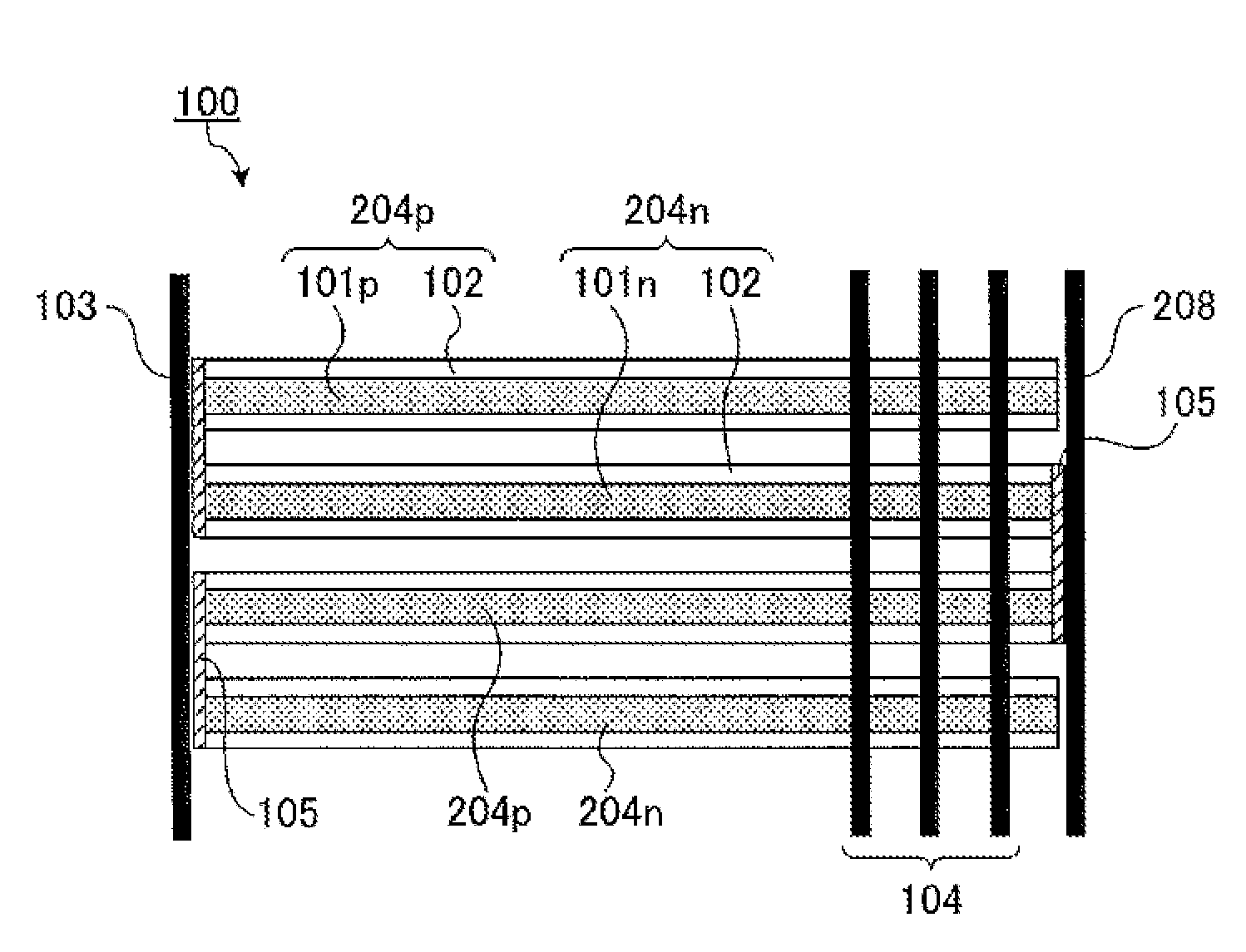
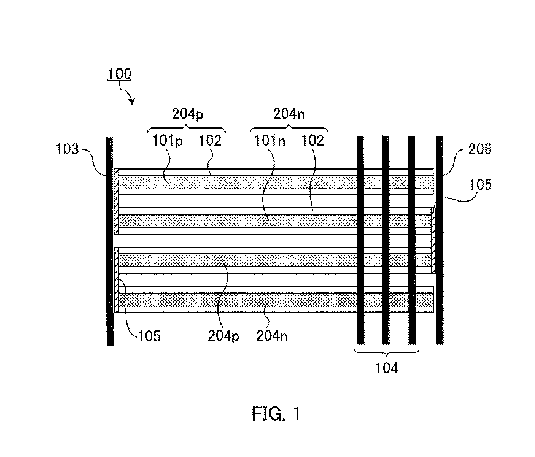
[0022]FIG. 1 is a schematic view of a thermoelectric conversion module according to Embodiment 1. In FIG. 1, thermoelectric conversion module 100 includes p-type thermoelectric conversion elements 204p and n-type thermoelectric conversion elements 204n, thermo-uniformity plate 103, heat-radiation fins 104, interconnects 105, and interconnection plate 208.

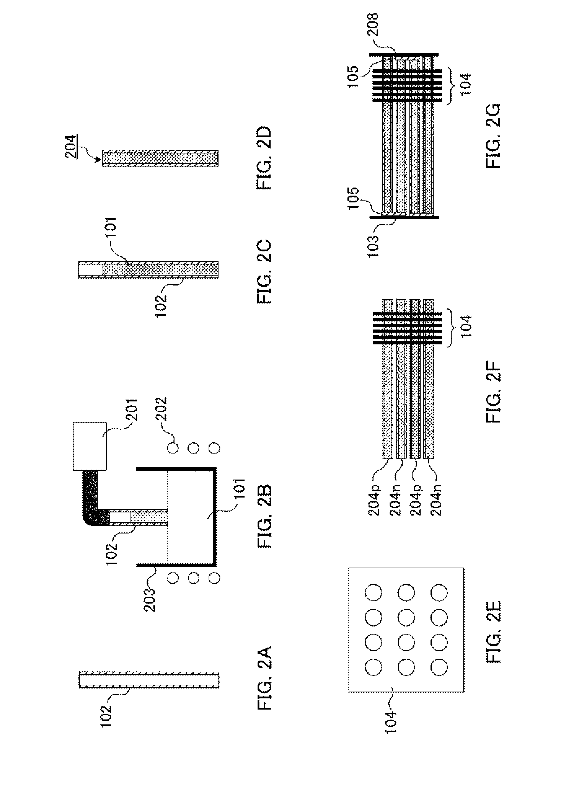
[0023]P-type thermoelectric conversion element 204p includes p-type thermoelectric conversion material 101p and tubular heat-resistant insulating material 102. N-type thermoelectric conversion element 204n includes n-type thermoelectric conversion material 101n and tubular heat-resistant insulating material 102. Interconnect 105 electrically connects p-type thermoelectric conversion material 101p of p-type thermoelectric conversion element 204p with n-type thermoelectric conversion material 101n of n-type thermoelectric convers...


PUM


Abstract

A thermoelectric conversion module in which a high-density disposition is easily performed and connection reliability is high is supplied. A thermoelectric conversion module is provided, which includes a plurality of p-type thermoelectric conversion elements and a plurality of n-type thermoelectric conversion elements that are alternately arranged. and electrically connected in series, and a plurality of heat-radiation fins that are disposed in one end side of the plurality of p-type thermoelectric conversion elements and the plurality of n-type thermoelectric conversion elements in side surfaces of the plurality of p-type thermoelectric conversion elements and the plurality of n-type thermoelectric conversion elements. The plurality of heat-radiation fins intersect the long axis directions of the p-type thermoelectric conversion elements and the n-type thermoelectric conversion element and connect the p-type thermoelectric conversion elements and the n-type thermoelectric conversion element to each other.

Description

CROSS REFERENCE TO RELATED APPLICATIONS[0001]This application is entitled to the benefit of Japanese Patent Application No. 2012-084548, filed Apr. 3, 2012, and Japanese Patent Application No. 2013-021388, filed Feb. 6, 2013, the entire contents of which are incorporated by reference herein.TECHNICAL FIELD[0002]The present invention relates to a thermoelectric conversion module.BACKGROUND ART[0003]A thermoelectric conversion element is an element which performs conversion between heat and electric power using Peltier effect or Seeback effect. In the thermoelectric conversion element, since the structure is simple, the handling is easy, and stable characteristics can be maintained, recently, the extensive use attracts attention. When the thermoelectric conversion element is used as an electronic cooling element, local cooling or an accurate temperature control in the vicinity of room temperature can be performed. Thereby, research has been widely processed for making temperature of a...

Claims


Application Information

Patent Timeline
IPC IPC(8): H01L35/30H01L35/32
CPCH01L35/30H01L35/32H10N10/17H10N10/13
Inventor HIGASHIDA, TAKAAKIKUBO, TAKASHIOHIDO, YOSHIHISATOYODA, KAORIMAESHIMA, SATOSHI
Owner PANASONIC INTELLECTUAL PROPERTY MANAGEMENT CO LTD
Learn More