
Conductor pattern forming method

Inactive Publication Date: 2012-06-07
NGK SPARK PLUG CO LTD
View PDF4 Cites 0 Cited by
  • Summary
  • Abstract
  • Description
  • Claims
  • Application Information

AI Technical Summary

Benefits of technology

[0005]It is therefore an object of the present invention to provide a conductor pattern forming method by which a conductor can be formed with high connection reliability. It is also an object of the present invention to provide a gas sensor manufacturing method in which an electrode pattern of a gas sensor element is formed by the above conductor pattern forming method.

Problems solved by technology

In the ink-jet printing process, however, any one or some of the nozzles of the ink-jet head may be clogged depending on the state of the printing ink and the operating condition of the ink-jet head.
When the ink jet printing process is adopted as the conductor pattern forming technique, there occurs a deterioration in the connection reliability of the conductor pattern or a breakage of the conductor pattern due to such nozzle clogging.

Method used


Image

  • Conductor pattern forming method
  • Conductor pattern forming method
  • Conductor pattern forming method

Examples


examples

[0052]The present invention will be described in more detail below by way of the following examples.

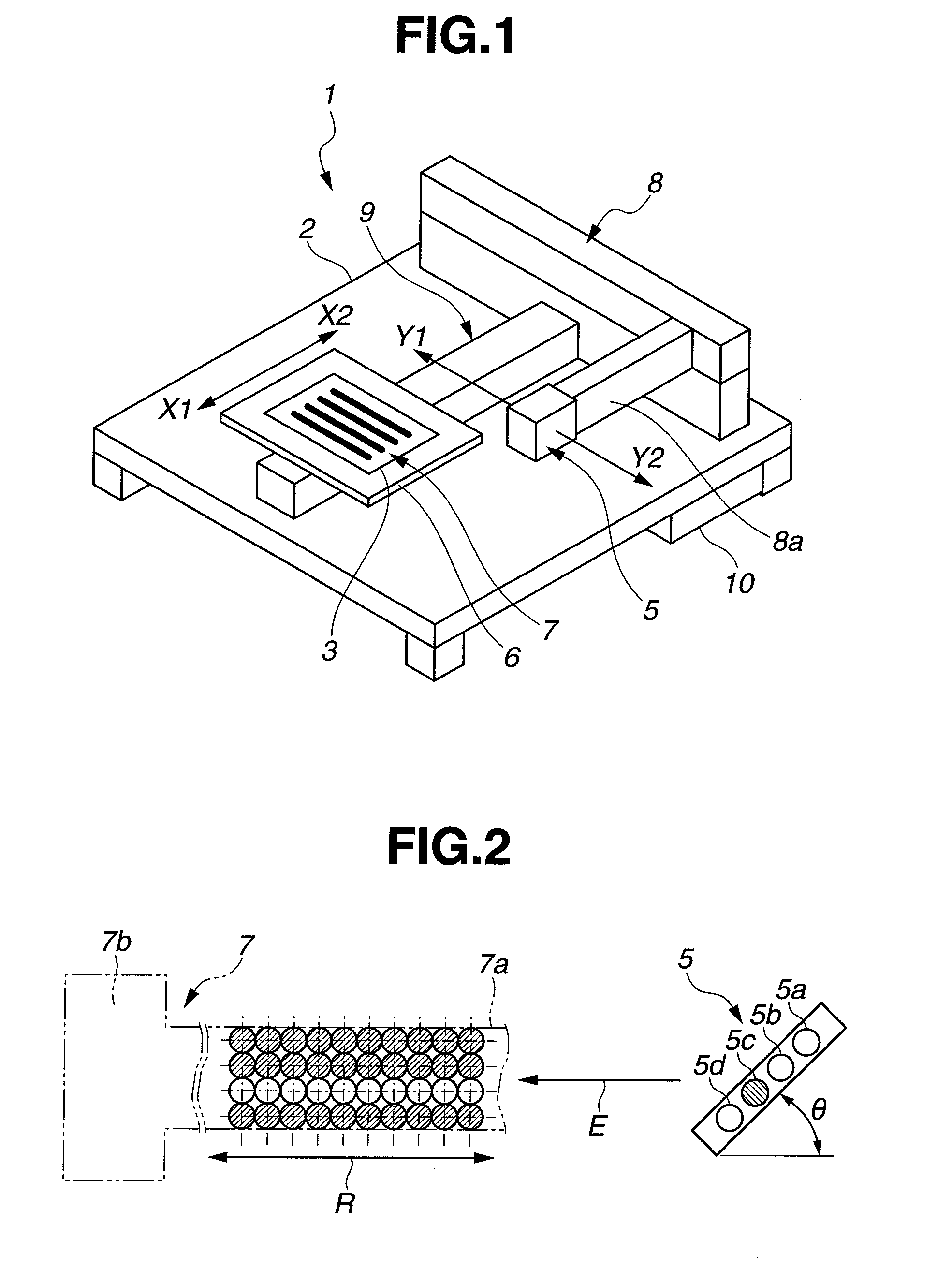
[0053]In each of Examples 1 and 2 and Comparative Examples 1 and 2, a conductor pattern 90 was formed by ink jet printing on a substrate as shown in FIG. 5. Herein, the conductor pattern 90 had six pattern lines arranged in parallel at a given pitch P and each having a length L of 50 mm and a width W of 1 mm. The ink-jet printing was performed by means of the printing device 1 of FIG. 1 where the print head (ink-jet head) had 10 nozzles arranged at a pitch of 508 μm. Further, there was used a liquid printing ink containing 66 mass % of butyl carbitol acetate as a solvent, 28 mass % of platinum as a metal, 4 mass % of zirconia as a metal oxide, 1 mass % of a binder and 1 mass % of a dispersant etc.

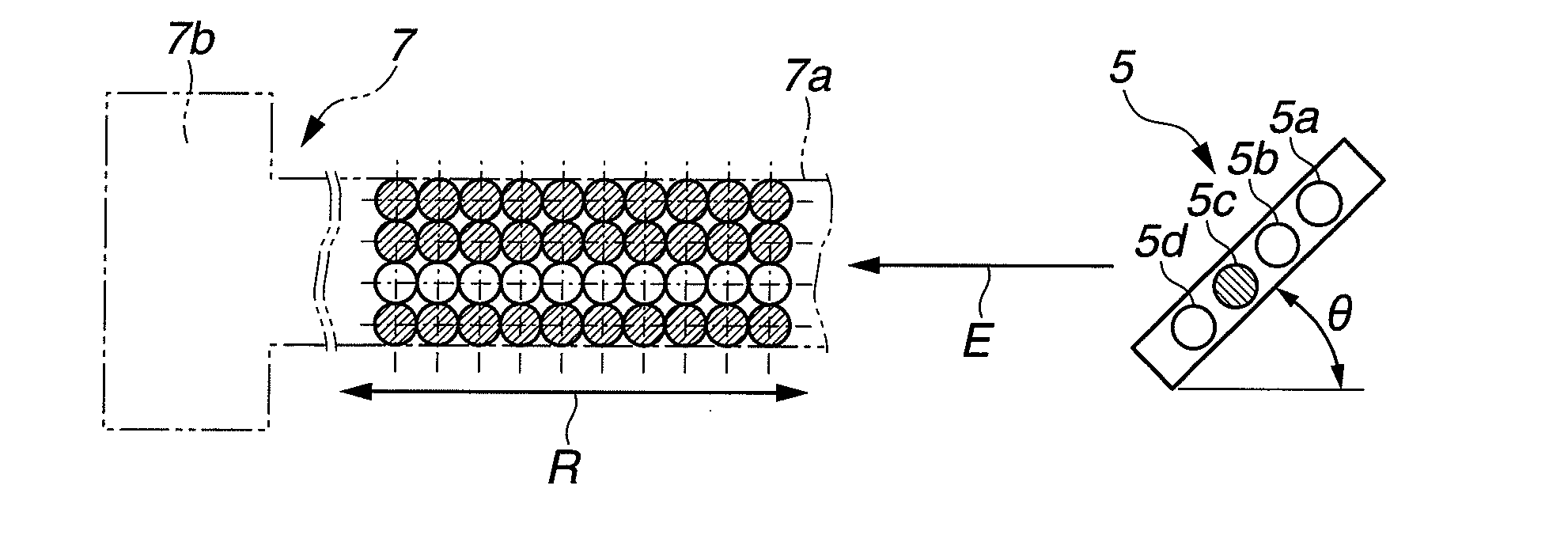
[0054]In Examples 1 and 2, the ink-jet printing was performed in a direction E along the longitudinal direction of the conductor pattern 90 (7) as shown in FIG. 2. In Comparative Examples 1 a...


PUM


Abstract

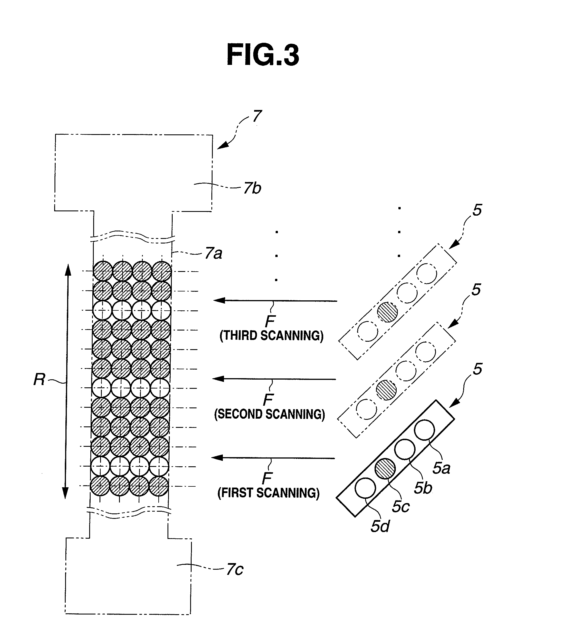
There is provided a method for forming a conductor pattern on a substrate in such a manner that the conductor pattern has a lead portion extending in a longitudinal direction thereof, a first conductor portion located at one end of the lead portion and a second conductor portion located at the other end of the lead portion, including a printing step of printing at least the lead portion by ink-jet printing process, i.e., scanning a print head while discharging liquid ink drops from nozzles of the prink head, wherein the scanning of the print head is performed in the longitudinal direction of the conductor pattern during the printing step; and wherein the length of each of the first and second conductor portions in a direction perpendicular to the longitudinal direction of the conductor pattern is larger than the diameter of the ink drop.

Description

BACKGROUND OF THE INVENTION[0001]The present invention relates to a method for forming a conductor pattern.[0002]There is conventionally known ink-jet printing process in which a given ink pattern is printed on a print object such as a print paper or a substrate by means of an ink-jet head and, more specifically, by moving the print object in one direction while moving the ink-jet head in a direction perpendicular to the moving direction of the print object as disclosed in Japanese Laid-Open Patent Publication No. 2006-35820. In this printing process, the relative moving direction of the print object and the ink-jet head, i.e., the actual direction of pattern printing on the print object is always constant regardless of the pattern orientation (horizontal orientation or vertical orientation). Further, the ink-jet head is generally configured to, while moving the print object on a stage, apply pressure pulses to a molten ink and thereby discharge minute ink drops from its nozzles (in...

Claims


Application Information

Patent Timeline
IPC IPC(8): B05D5/12
CPCB41J2/2132H05K1/16H05K2201/10151H05K3/4629H05K3/125
Inventor MORI, KENTAROUEMATSU, DAISUKEHAYAKAWA, NOBUHIRO
Owner NGK SPARK PLUG CO LTD
Learn More