Offset Window Fan

a window fan and offset technology, applied in the field of room temperature control, can solve the problems of thinness of windows and very little resistan

Active Publication Date: 2020-01-16
AQUINO ANTONIO
View PDF5 Cites 3 Cited by
  • Summary
  • Abstract
  • Description
  • Claims
  • Application Information

AI Technical Summary

Benefits of technology

[0005]The present invention addresses the above and other needs by providing an offset window mount fan including two or more independently controlled fans controllable to move air in the same direction or in opposite directions. A housing substantially offsets the fans from a direct passage of air into the room. In one embodiment, the fans are mounted in a housing perpendicular to the window, air traveling through the fans turning 90 degrees to pass through the plane of the window and 90 degrees down into the room. Each fan includes a temperature sensor to measure temperature of air moving through each fan. The fans are energized periodically for a short time period to make accurate temperature measurements. When the combined temperature measurements indicate an advantage from fan operation, the fans are activated.
[0006]In accordance with one aspect of the invention, there is provided an offset window fan housing having an outside portion containing at least one fan. The housing positions the partially, or totally offset from the window. In one embodiment, a housing has a narrow horizontal waist portion resting on a window sill, an exterior portion outside the window turning down, and an interior portion inside the room and turning down. At least one fan is in the exterior portion and has a fan axis (the direction air flows) perpendicular to the window. The thin waist portion minimizes the window area blocked by the fan and the downward interior and exterior portions prevent or reduce air flow due to wind.

Problems solved by technology

In many instances, the fan is operated when outside air is above the inside air temperature when cooling is desired or below the inside air temperature when heating is desired, providing an undesirable result.
Further, window fans are generally thin and have very little resistance to air passing through the fan when the fan is not on.
On a windy day, either hot or cold outside air may enter the room creating an undesired result.

Method used


Image

  • Offset Window Fan
  • Offset Window Fan
  • Offset Window Fan

Examples


Embodiment Construction

[0027]The following description is of the best mode presently contemplated for carrying out the invention. This description is not to be taken in a limiting sense, but is made merely for the purpose of describing one or more preferred embodiments of the invention. The scope of the invention should be determined with reference to the claims.

[0028]Where the terms “about” or “generally” are associated with an element of the invention, it is intended to describe a feature's appearance to the human eye or human perception, and not a precise measurement.

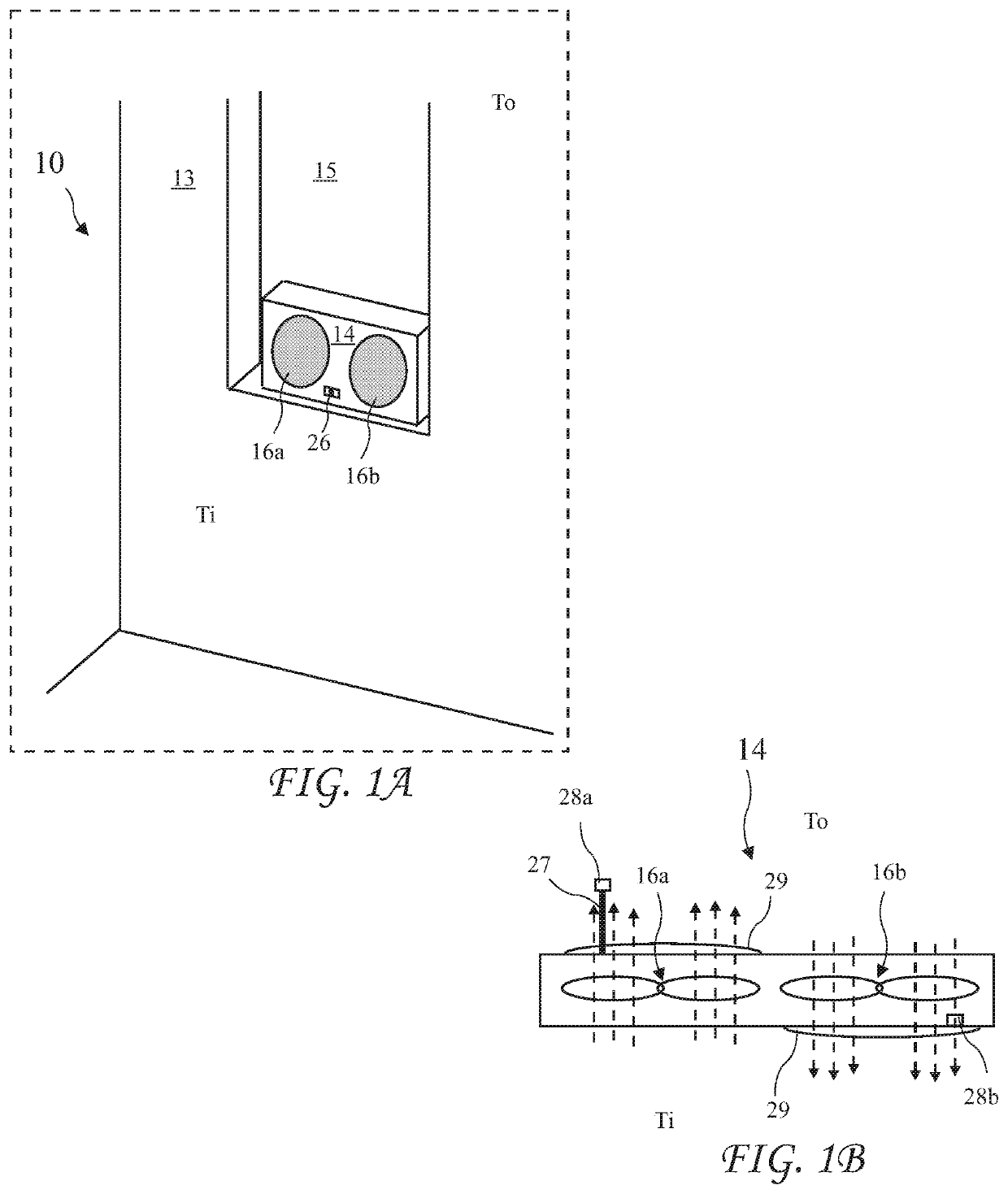
[0029]A temperature controlled area 10 including a dual wall fan (for example a window fan) 14 according to the present invention are shown in FIG. 1A and a top view of the dual wall fan 14 in operation is shown in FIG. 1B. The dual wall fan 14 is mounted to an external wall 13, preferably in windows 15. The dual wall fan 14 includes controls 26, preferably as part of dual wall fan 14 (but may be wired or wireless remote controls), electri...


PUM


Abstract

An offset window mount fan includes two or more independently controlled fans controllable to move air in the same direction or in opposite directions. A housing substantially offsets the fans from a direct passage of air into the room. In one embodiment, the fans are mounted in a housing perpendicular to the window, air traveling through the fans turning 90 degrees to pass through the plane of the window and 90 degrees down into the room. Each fan includes a temperature sensor to measure temperature of air moving through each fan. The fans are energized periodically for a short time period to make accurate temperature measurements. When the combined temperature measurements indicate an advantage from fan operation, the fans are activated.

Description

CROSS-REFERENCE TO RELATED APPLICATIONS[0001]The present application is a Continuation In Part of U.S. patent application Ser. No. 16 / 036,266 filed Jul. 16, 2018, which application is incorporated in its entirety herein by reference.BACKGROUND OF THE INVENTION[0002]The present invention relates to room temperature control and in particular to wall mounted fans.[0003]Wall mounted fans are often used to provide cool outside air to a room when cooling is desired, or warm outside air to a room when heating is desired. The fans generally compare room temperature to a temperature setting, and activate the fan when the room temperature exceeds the setting for cooling and activate the fan when room temperature is less than the setting for heating. In many instances, the fan is operated when outside air is above the inside air temperature when cooling is desired or below the inside air temperature when heating is desired, providing an undesirable result.[0004]Further, window fans are general...

Claims


Application Information

Patent Timeline
Patent Type & Authority Applications(United States)
IPC IPC(8): F24F11/00
CPCF24F11/0001F24F7/013F24F11/74F24F11/79F24F2110/10
Inventor AQUINO, ANTONIO
Owner AQUINO ANTONIO
Why Eureka
Try Eureka