Fluorescent light bulb and manufacturing method thereof

a technology of fluorescent light bulbs and manufacturing methods, which is applied in the manufacture of electric discharge tubes/lamps, discharge tubes luminescnet screens, electrode systems, etc., can solve the problems of substantial loss of illumination (i.e. brightness) substantial waste of energy, and substantial blockage of light at the inner of fluorescent light tubes, so as to improve efficiency and enhance brightness

Inactive Publication Date: 2009-12-10
BOSS SUPER ENERGY SAVING LIGHTING
View PDF9 Cites 0 Cited by
  • Summary
  • Abstract
  • Description
  • Claims
  • Application Information

AI Technical Summary

Benefits of technology

[0007]A main object of the present invention is to provide a method of manufacturing a fluorescent light bulb wherein the fluorescent light bulb is capable of delivering illumination with enhanced brightness and increased efficiency.
[0008]Another object of the present invention is to provide a method of manufacturing a fluorescent light bulb comprising a plurality of elongated fluorescent elements spacedly mounted on a lighting base, in such a manner that the light blocked by an inner side of each of the elongated fluorescent elements are minimized so as to maximize an efficiency and effectiveness of light generation by the fluorescent light bulb.
[0009]Another object of the present invention is to provide a method of manufacturing a fluorescent light bulb which utilizes a minimum number of elongated fluorescent elements for a given brightness. In other words, the present invention simplifies the conventional manufacturing methods and the structure of conventional fluorescent light bulbs.
[0010]Another object of the present invention is to provide a method of manufacturing a fluorescent light bulb which is simple and convenient so as to allow a user of the present invention to manufacture the fluorescent light bulb with minimum cost and labor.
[0023](e) electrically coupling fluorescent terminals at the fluorescent elements with the electrical terminals of the lighting base, wherein when the fluorescent elements are electrified, each of the fluorescent tubes is adapted for generating fluorescent light at an outer surface thereof not only to increase a light projecting angle at the curving portion of each of the fluorescent tubes but also to allow the fluorescent light from the opposed fluorescent element passing through the light passageway so as to enhance a brightness and efficiency of the fluorescent elements.

Problems solved by technology

There are several disadvantages regarding this type of conventional fluorescent light bulb.
While this design may maximize the surface area from which illumination can be delivered, there exists substantial loss of illumination (i.e. brightness) from the fluorescent light tube because an inner side of the spirally extending fluorescent light tube is not exposed to the ambient environment.
As a result, light is substantially blocked at the inner of the fluorescent light tube which constitutes substantial waste of energy and unsatisfactory performance of the fluorescent light bulb as a whole.
Moreover, when the fluorescent light tube is made in a spirally extending manner, the manufacturing process of the fluorescent light bulb is inherently complicated.
The reason of this kind of design may be due to the fact that a single U-shaped fluorescent light tube is unable to produce sufficient illumination.
The problem with this kind of design is that the fluorescent light tubes are so crowdedly packed that a substantial amount of illumination is blocked at the inner side of the supporting base in a similar manner as described above.

Method used


Image

  • Fluorescent light bulb and manufacturing method thereof
  • Fluorescent light bulb and manufacturing method thereof
  • Fluorescent light bulb and manufacturing method thereof

Examples


Embodiment Construction

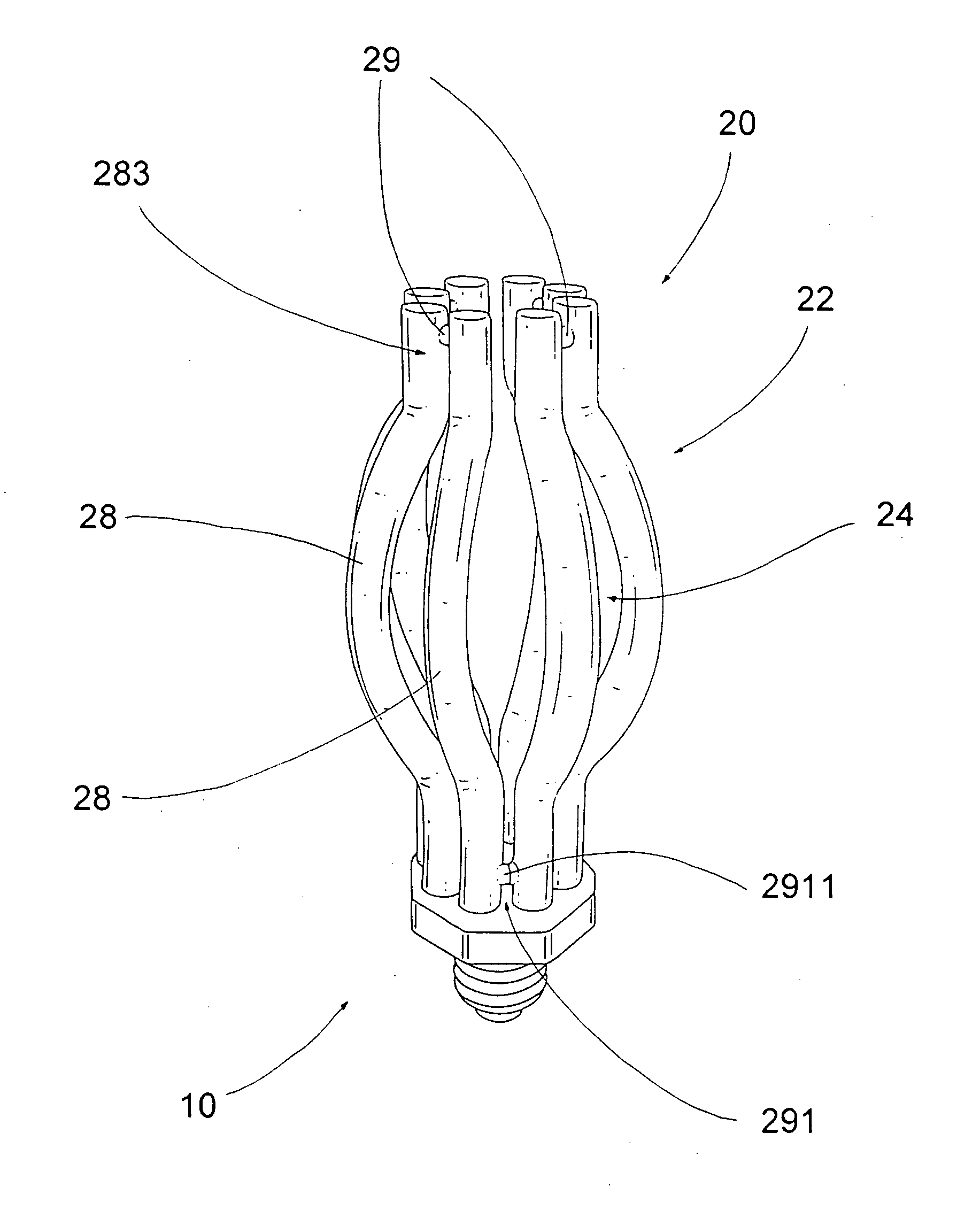
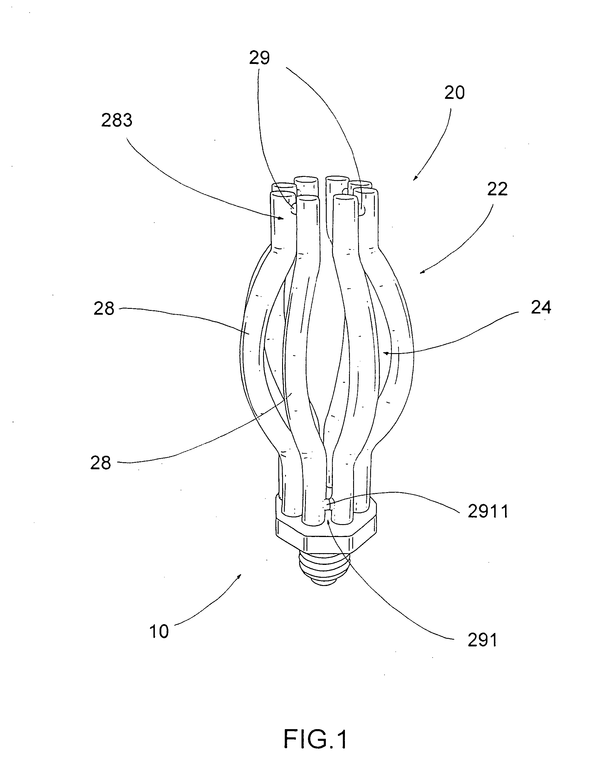
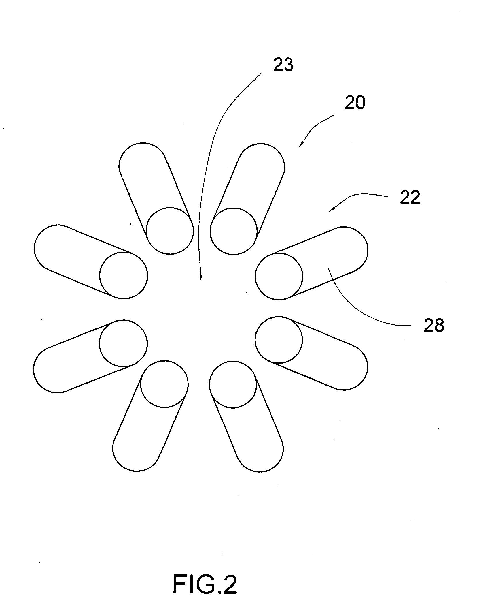
[0034]Referring to FIG. 1 to FIG. 4 of the drawings, a fluorescent light bulb and its manufacturing method according to a preferred embodiment of the present invention is illustrated, in which the fluorescent light bulb comprises a lighting base 10 and a fluorescent illuminating structure 20. As shown in the drawings, the lighting base 10 has a plurality of electrical terminals 11.

[0035]The fluorescent illuminating structure 20 comprises at least two fluorescent terminals 21 electrically coupling with the electrical terminals 11 and a plurality of elongated fluorescent elements 22 spacedly, upwardly and radially extended from the lighting base 10 to define a light passage cavity 23 within the fluorescent elements 22, wherein each of the fluorescent elements 22 comprises two elongated fluorescent tubes 28 filled with illuminating reactive agent and an communicating extension 29 communicatively extended between the fluorescent tubes 28, wherein each of the fluorescent tubes 28 has a l...


PUM


Abstract

A method of manufacturing a fluorescent light bulb includes the steps of: (a) providing a lighting base which has a plurality of electrical terminals formed thereon; (b) bending an elongated fluorescent tube to form a lower vertical-extending portion and an upper curving portion outwardly and radially extended from the vertical-extending portion; (c) communicatively linking every two of the fluorescent tubes to form a plurality of fluorescent elements, wherein a light passageway is formed between the two curving portions of the fluorescent tubes of each of the fluorescent elements; (d) mounting the fluorescent elements at the lighting base; and (e) electrically coupling the fluorescent elements with the lighting base, so as to allow the fluorescent light from the opposed fluorescent element to pass through the light passageway so as to enhance a brightness and efficiency of the fluorescent elements.

Description

BACKGROUND OF THE PRESENT INVENTION[0001]1. Field of Invention[0002]The present invention relates to a light bulb, and more particularly to a fluorescent light bulb and the manufacturing method thereof, wherein the fluorescent light bulb is capable of delivering illumination with enhanced brightness and increased efficiency.[0003]2. Description of Related Arts[0004]A conventional fluorescent light bulb usually comprises a supporting base and a fluorescent light tube mounted on top of the supporting base, wherein the supporting base is arranged to electrically connect to a power source for electrically activating the fluorescent light tube to generate illumination.[0005]There are several disadvantages regarding this type of conventional fluorescent light bulb. First, as a matter of conventional art, most of the fluorescent light tube is made to extend on the supporting base in a spiral manner. While this design may maximize the surface area from which illumination can be delivered, t...

Claims


Application Information

Patent Timeline
Patent Type & Authority Applications(United States)
IPC IPC(8): H01J63/04H01J9/02
CPCH01J9/247H01J61/94H01J61/327H01J61/20
Inventor GE, BAOGUIGE, WEI
Owner BOSS SUPER ENERGY SAVING LIGHTING
Why Eureka
Try Eureka