Method for manufacturing separator, separator manufactured therefrom, and electrochemical device comprising the same

a technology of separator and separator plate, which is applied in the manufacture of final product, cell component details, cell components, etc., can solve the problems of thermal runaway, complicated fabrication, and safety problems of lithium ion batteries, so as to prevent the transferring rate of lithium ions from being reduced, reduce the blockage of pores, and improve the adhesion

Active Publication Date: 2019-05-28
LG ENERGY SOLUTION LTD +1
View PDF26 Cites 1 Cited by
  • Summary
  • Abstract
  • Description
  • Claims
  • Application Information

AI Technical Summary

Benefits of technology

[0025]The separator of the present invention exhibits the following effects.
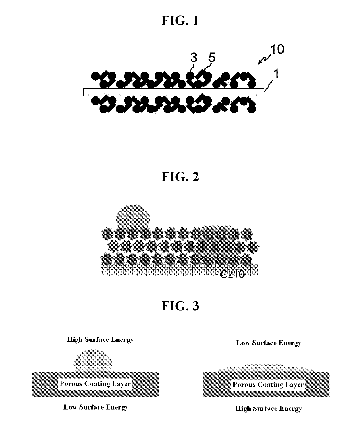
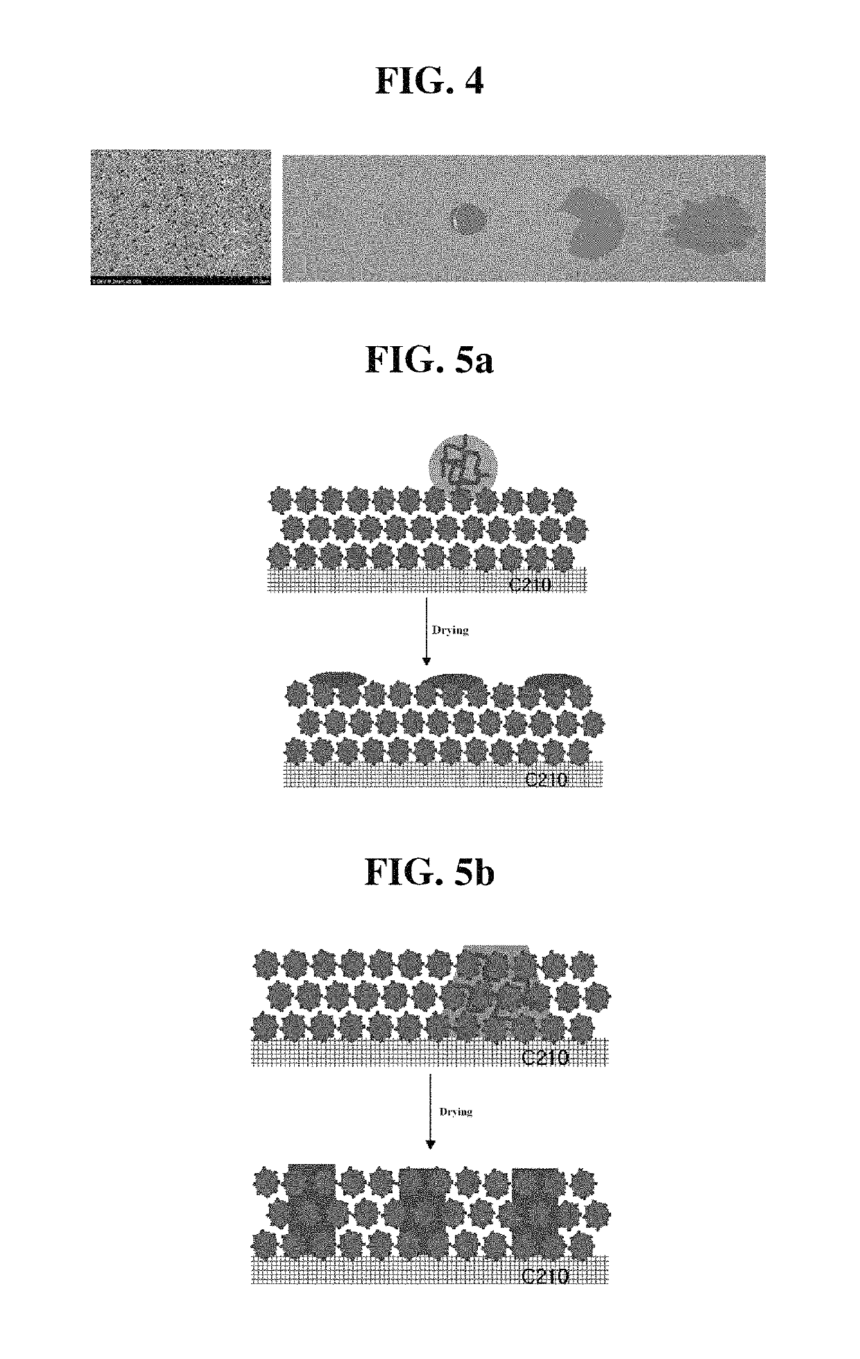
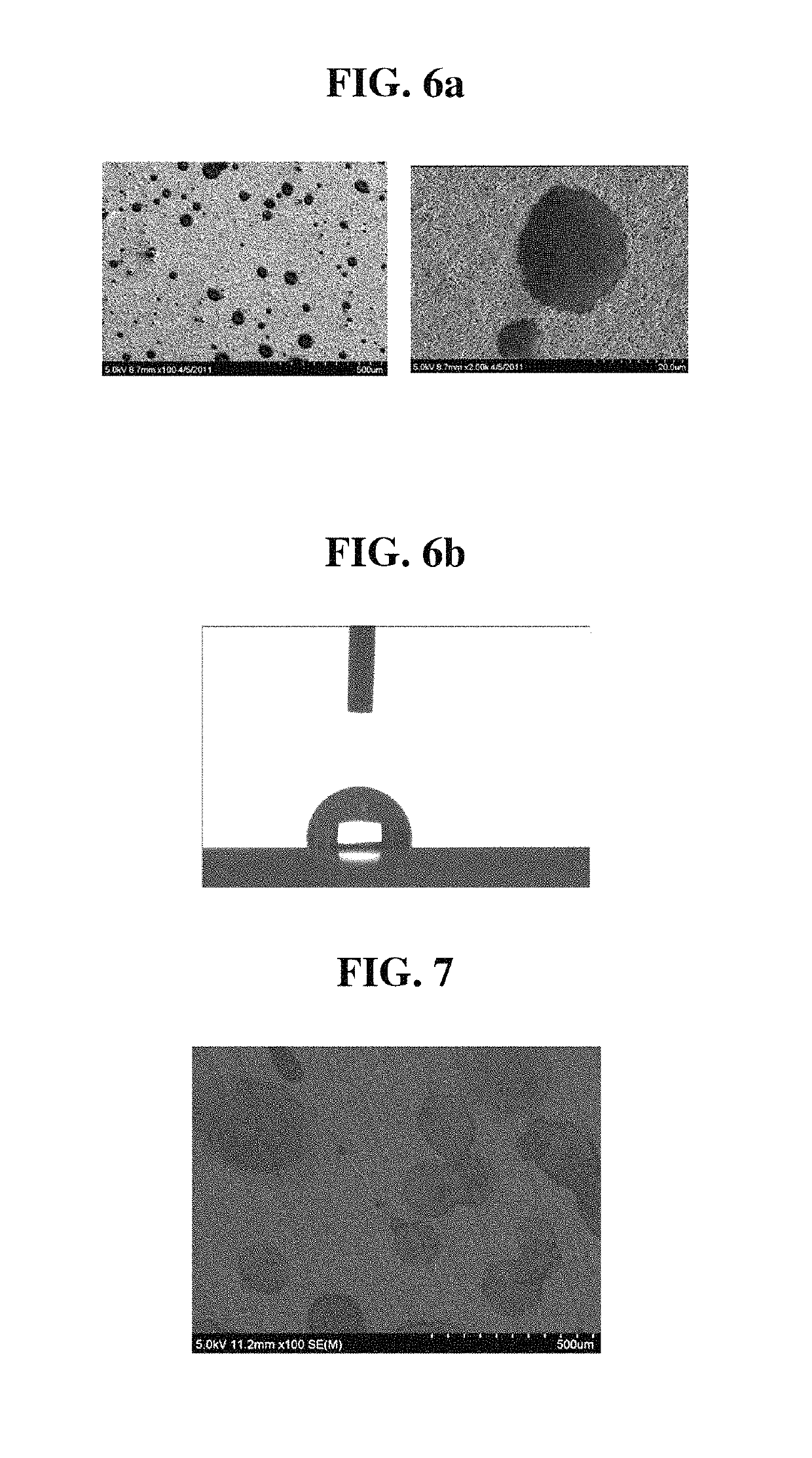
[0026]First, an adhesive layer is formed by applying a binder solution on the surface of a porous coating layer so that the contact angle of the binder solution to the surface of the porous coating layer is maintained at 80° or more for 30 seconds, thereby minimizing the blockage of the pores of the separator and significantly preventing the transferring rate of lithium ions from being reduced, and ultimately improving an adhesion with an electrode as well as reducing resistance.
[0027]Second, the binder solution has a higher surface energy than that of the porous coating layer to form the adhesive layer, which is configured for adhesion with an electrode, in a locally narrow area, thereby obtaining sufficient adhesion force with minimizing the amount of an electrode adhesive.
[0028]Third, as the binder of the electrode-adhesive layer is minimized, a minimum amount of the binder comes in contact with an electrode, thereby preventing the deterioration of battery performances.

Problems solved by technology

However, such lithium ion batteries suffer from safety problems, such as fire and explosion, when encountered with the use of organic electrolytes and are disadvantageously complicated to fabricate.
Overheating of an electrochemical device may cause thermal runaway or a puncture of a separator may pose an increased risk of explosion.
This thermal shrinkage behavior may cause electrical short between a cathode and an anode.

Method used


Image

  • Method for manufacturing separator, separator manufactured therefrom, and electrochemical device comprising the same
  • Method for manufacturing separator, separator manufactured therefrom, and electrochemical device comprising the same
  • Method for manufacturing separator, separator manufactured therefrom, and electrochemical device comprising the same

Examples


example 1

[0086]To acetone, polyvinylidene fluoride-co-hexafluoropropylene (PVdF-HFP) copolymer as a polymer was added in an amount of 5 wt % and dissolved at 50° C. for about 12 hours or more to prepare a binder polymer solution. To the binder polymer solution, Al2O3 powders were added so that the weight ratio of the binder polymer and the Al2O3 powders is 10:90, and the Al2O3 powders were pulverized and dispersed for 12 hours or more by means of a ball mill to prepare a slurry. The particle size of Al2O3 present in the slurry prepared thus was about 400 nm. The slurry was coated on a porous polyethylene membrane having a thickness of 12 μm and a porosity of 45% by way of a dip coating method, and the coating thickness was controlled in a thickness of about 20 μm.

[0087]The porous coating layer formed on the porous polyethylene membrane was measured for its pore size and porosity by means of a porosimeter, and as a result, the pore size and the porosity of the porous coating layer were 0.4 μm...

example 2

[0094]The procedures of Example 1 were repeated except that a binder solution obtained by dissolving 10 parts by weight of polyvinyl pyrrolidone (Aldrich, Mw: 55,000) in 100 parts by weight of water was used, to prepare a separator having an adhesive layer.

[0095]In the separator, the contact angle of the binder solution to the porous coating layer was maintained at 85° for 30 seconds.

example 3

[0096]The procedures of Example 1 were repeated except that a binder solution obtained by dissolving 10 parts by weight of polyethylene glycol (Aldrich, Mw: 8,000) in 100 parts by weight of water was used, to prepare a separator having an adhesive layer.

[0097]In the separator, the contact angle of the binder solution to a surface of the porous coating layer was maintained at 93° for 30 seconds.


PUM

PropertyMeasurementUnit
contact angleaaaaaaaaaa
surface energyaaaaaaaaaa
thicknessaaaaaaaaaa

Abstract

The present invention provides a method for manufacturing a separator, comprising the steps of (S1) preparing a porous planar substrate having multiple pores; (S2) coating a coating solution obtained by dissolving a binder polymer in a solvent and dispersing inorganic particles therein on the porous substrate to form a porous coating layer and drying the porous coating layer; and (S3) applying a binder solution on the surface of the dried porous coating layer to form an adhesive layer, wherein the binder solution has a surface energy of at least 10 mN / m higher than that of the porous coating layer and a contact angle of the binder solution to the surface of the porous coating layer maintained at 80° or more for 30 seconds. In accordance with the present invention, a separator capable of obtaining sufficient adhesion force with minimizing the amount of an adhesive used for the adhesion with an electrode, and minimizing the deterioration of battery performances can be easily manufactured.

Description

CROSS-REFERENCE TO RELATED APPLICATION[0001]This application is a continuation of International Application No. PCT / KR2012 / 011379 filed on Dec. 24, 2012, which claims priority to Korean Patent Application No. 10-2011-0143759 filed in the Republic of Korea on Dec. 27, 2011, and Korean Patent Application No. 10-2012-0150587 filed in the Republic of Korea on Dec. 21, 2012, the disclosures of which are incorporated herein by reference.TECHNICAL FIELD[0002]The present invention relates to a method for manufacturing a separator, a separator manufactured therefrom, and an electrochemical device comprising the separator. More particularly, the present invention relates to a method for manufacturing a separator, characterized by the formation of an adhesive layer by way of applying a binder solution whose surface energy is at least 10 mN / m higher than that of a porous coating layer and contact angle to the surface of the porous coating layer is maintained at 80° or more for 30 seconds, a sep...

Claims


Application Information

Patent Timeline
Patent Type & Authority Patents(United States)
IPC IPC(8): H01M2/14H01M2/16H01M50/403H01M50/414H01M50/417H01M50/434H01M50/449
CPCH01M2/145H01M2/166H01M2/1653H01M2/1686H01M2/1646H01M2/168H01M50/403H01M50/446H01M50/461H01M50/449H01M50/414H01M50/417H01M50/434Y02E60/10Y02P70/50H01M50/491H01M50/489H01M50/443H01M50/431H01M10/052
Inventor HA, JEONG-MINLEE, JOO-SUNGKIMKIM, JONG-HUNJIN, SUN-MIRYU, BO-KYUNG
Owner LG ENERGY SOLUTION LTD
Why Eureka
Try Eureka