
Multifunction peripheral capable of properly executing a plurality of processes, method of controlling same, and storage medium

Active Publication Date: 2020-01-16
CANON KK
View PDF15 Cites 4 Cited by
  • Summary
  • Abstract
  • Description
  • Claims
  • Application Information

AI Technical Summary

Benefits of technology

[0009]The present invention provides a multifunction peripheral that is capable of properly executing a plurality of processes including a scanning process and enabling a

Problems solved by technology

However, if the speed of the scanning process of the multifunction peripheral is increased, the load of data transfer from the scanner section to the image memory is increased.
This may make it difficult for the multifunction peripheral increased in the speed of the scanning

Method used


Image

  • Multifunction peripheral capable of properly executing a plurality of processes, method of controlling same, and storage medium
  • Multifunction peripheral capable of properly executing a plurality of processes, method of controlling same, and storage medium
  • Multifunction peripheral capable of properly executing a plurality of processes, method of controlling same, and storage medium

Examples


first embodiment

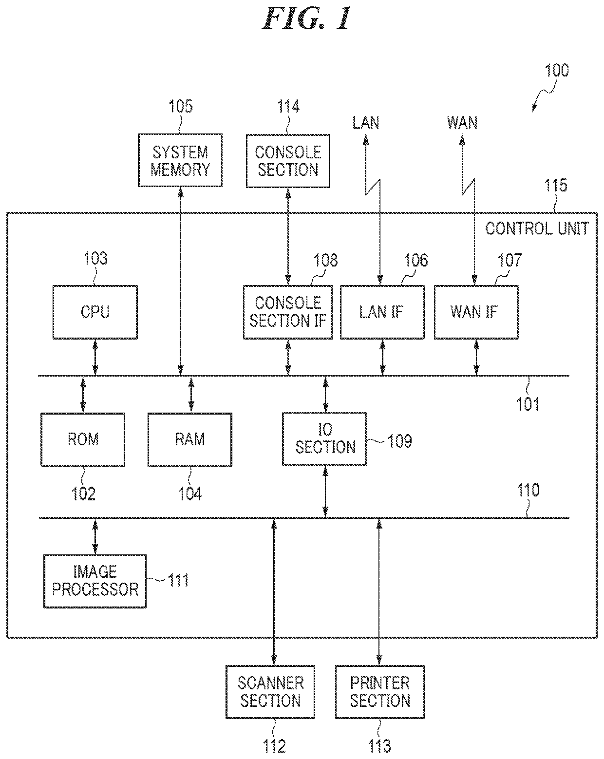
[0033]FIG. 1 is a schematic diagram of a multifunction peripheral 100 according to the present invention.

[0034]The multifunction peripheral 100 shown in FIG. 1 includes a scanner section 112 that scans an original to generate image data, a printer section 113 that prints image data on a sheet, a console section 114, a control unit 115, and a system memory 105.

[0035]The console section 114 is a user interface, and includes an LCD touch panel, numeric keys, and so forth. The LCD touch panel displays a setting screen, and so forth. The LCD touch panel, numeric keys, and so forth, are operated by a user.

[0036]The control unit 115 includes two buses, a system bus 101 and an image bus 110.

[0037]A CPU 103, a ROM 102, a RAM 104, the system memory 105, a console section interface 108, a LAN interface 106, a WAN interface 107, and an IO section 109 are connected to the system bus 101.

[0038]A system boot program is recorded in the ROM 102.

[0039]The system memory 105 as a configuration memory i...

second embodiment

[0176]FIG. 13 is a flowchart useful in explaining execution of a scanning process in the

[0177]The CPU 103 of the control unit 115 performs the process in FIG. 13 when the scanning process by the scanner section 112 is started.

[0178]In a step S1301 in FIG. 13, the CPU 103 of the control unit 115 acquires settings for reading an original.

[0179]In a step S1302, the CPU 103 determines an ASIC of the image processor 111, which is to be used for executing the scanning process based on the reading settings acquired in the step S1301, and makes settings of the ASIC to be used.

[0180]In a step S1303, the CPU 103 as the parallel determination unit determines whether or not any process other than the scanning process is being executed or on standby.

[0181]If any other process is not being executed or on standby, the CPU 103 proceeds to a step S1315.

[0182]In the step S1315, the CPU 103 notifies the scanner section 112 and the JO section 109 that the operation of the scanning process is to be star...


PUM


Abstract

A multifunction peripheral that is capable of performing, in parallel, a plurality of processes including a scanning process on an original using a scanner section. A RAM holds image data generated by the scanner section. A scanner transfer section transfers data from the scanner section to the RAM. A transfer rate of data from the scanner section to the RAM is set by switching at least between a first transfer rate and a second transfer rate lower than the first transfer rate. In a case where a plurality of processes including the scanning process are executed in parallel, a data transfer rate is switched by switching the data transfer rate based on a user's operation performed on a console section.

Description

BACKGROUND OF THE INVENTIONField of the Invention[0001]The present invention relates to a multifunction peripheral that is capable of properly executing a plurality of processes, a method of controlling the same, and a storage medium.Description of the Related Art[0002]For example, a multifunction peripheral includes a scanner section, an image processor, a printer section, and a communication section.[0003]The multifunction peripheral scans an original, prints image data, and performs facsimile communication by combining processes performed by the sections and processor.[0004]For example, in a case where an image of an original is copied to a sheet, first, the multifunction peripheral reads the original, and transfers image data of the read original to an image memory using the scanner section. Next, the multifunction peripheral converts the image data in the image memory to data for printing using the image processor. Next, the multifunction peripheral prints the converted image d...

Claims


Application Information

Patent Timeline
IPC IPC(8): H04N1/00H04N1/32
CPCH04N1/32673H04N1/00652H04N2201/0094H04N1/00411H04N1/00427H04N1/00482H04N1/32448H04N1/17Y02D10/00H04N1/0096H04N1/00811H04N1/00822H04N1/2338H04N1/2369H04N1/0443H04N1/0446H04N2201/0454
Inventor KASUYA, KENJI
Owner CANON KK
Learn More