One-piece drink-through cup lid with a straw section

Inactive Publication Date: 2020-01-23
CHOU JONATHAN
0 Cites 2 Cited by

AI-Extracted Technical Summary

Problems solved by technology

However, such long straws are single-use and made of unrecyclable and indecomposable plastics, causing serious outcomes to the environment.
Still, there is the problem of weak structure with such straws.
On the other hand, the straws have to be separately carried from the beverage cups and therefore it is common for the straws to be inadvertently fallen, forgotten or ignored.
In Taiw...

Method used

[0030]Further referring to FIGS. 3-5, the conic section 30 is shaped in a curve C gradually extending wider from the rim 23 to the peripheral surface 11 of the cup lid 10 to ensure better endurance of the drink-through cup lid 40, but the present invention is not limited to such application. In this embodiment, a diameter D of the cup lid 10 is 100 mm; if the diameter D of the cup lid 10 is 100 mm, a diameter D1 of the bottom periphery 21 of the conic section 20 is preferred to be 25-50 mm and a diameter D2 of the rim 23 is 15-25 mm And a height H1 from the bottom periphery 21 to the rim 23 can be arranged at 25-40 mm.
[0035]FIG. 7 is a practical application view of the present invention showing the drink-through cup lid 40 covering on the beverage cup 50. The drink-t...

Benefits of technology

[0014]With structures disclosed above, the present invention has a conic straw structure formed on the drink-through cup lid to ingeniously integrate a single-use drink-through cup lid with a conic straw section for the purpose of easy carrying of the beverage cup it is place...

Abstract

A one-piece drink-through cup lid with a straw section includes a conic section and a detachable tube section. The conic section is axially protruding at a center of the cup lid and forming a rim at a top surface of the conic section. The detachable tube section is axially protruding from the rim of the conic section with a closed surface at a top thereof and an annular tear line at a bottom periphery thereof. The conic section and the tube section are formed in one-piece to ensure the cup lid is fully closed and sealed for practical use, and when the tube section is removed by manually tearing along the tear line, a through hole is formed at a top of the conic section so as to form a conic straw section for easily consuming the drink.

Application Domain

Closure with auxillary devicesClosures with discharging device +3

Technology Topic

Image

  • One-piece drink-through cup lid with a straw section
  • One-piece drink-through cup lid with a straw section
  • One-piece drink-through cup lid with a straw section

Examples

  • Experimental program(1)

Example

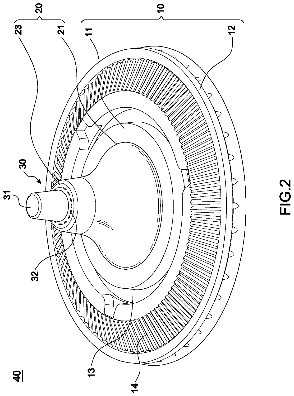
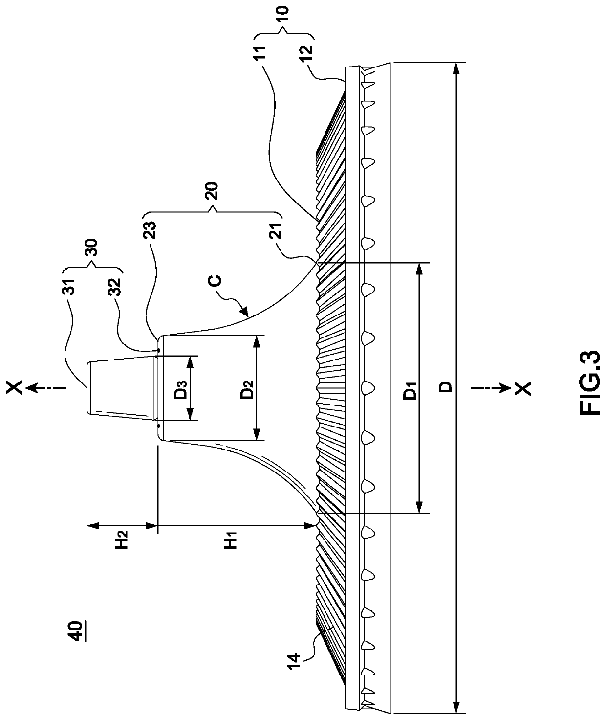
[0026]To further illustrate the features and structures of the drink-through cup lid, please referring to an embodiment in the following with reference to FIGS. 2-6B. A one-piece drink-through cup lid with a straw section 40 is designed for covering on a beverage cup 50. In the preferred embodiment, the one-piece drink-through cup lid with a straw section 40 mainly includes a cup lid 10, a conic section 20 and a detachable tube section 30 arranged on the conic section.
[0027]The cup lid 10 has a peripheral surface 11, a peripheral edge 12 extending from an outer edge of the peripheral surface 11, a circular depression 13 and a wavelike surface 14. Such structure can be commonly seen in conventional cup lids; however, the features of the present invention is that the conic section 20 is formed and protruding axially at a center of the peripheral surface 11 and has a bottom periphery 21 connecting to the peripheral surface 11 so as to form a first through hole 22 inside the conic section 20, and that a rim 23 is formed by having the conic section 20 extending outwardly from the bottom periphery 21. In this embodiment, the axial direction is shown in X-X line in the drawings.
[0028]The tube section 30 is extending axially from an inner periphery of the rim 23 and has a closed surface 31 at a top of the tube section 30 and a tear line 32 surrounding a bottom edge of the tube section 30 for detachment. In this embodiment, the tear line 32 is a broken line; but a V-shaped structure is also applicable as long as the tube section 30 can be easily torn and removed.
[0029]Thereby the tube section 30 and the conic section 20 are formed in one-piece to form a closed structure of the drink-through cup lid 40 and when the tube section 30 is torn along the tear line 32 and detached from the tube section 30, a second through hole 24 is formed at the top of the tube section 30; the second through hole 24 is further connecting through the first through hole 22 to form a conic straw section on the cup lid 10 for drinking through.
[0030]Further referring to FIGS. 3-5, the conic section 30 is shaped in a curve C gradually extending wider from the rim 23 to the peripheral surface 11 of the cup lid 10 to ensure better endurance of the drink-through cup lid 40, but the present invention is not limited to such application. In this embodiment, a diameter D of the cup lid 10 is 100 mm; if the diameter D of the cup lid 10 is 100 mm, a diameter D1 of the bottom periphery 21 of the conic section 20 is preferred to be 25-50 mm and a diameter D2 of the rim 23 is 15-25 mm And a height H1 from the bottom periphery 21 to the rim 23 can be arranged at 25-40 mm.
[0031]In addition, a diameter D3 of the tube section 30 is 8-16 mm and a height 112 from the rim 23 to the closed surface 31 of the tube section 30 is preferred to be 10-20 mm, but the present invention is not limited to such application.
[0032]Therefore, we can learn that the diameter D1 of bottom periphery D of the conic section 20 is 25-50% long of the diameter D of the cup lid 10; the diameter D2 of the rim 23 of the conic section 20 is 15-25% long of the diameter D of the cup lid D; the height H1 from the bottom periphery 21 to the rim 23 is 25-40% long of the diameter D of the cup lid 10; the diameter D3 of the tube section 30 is 8-16% long of the diameter D of the cup lid 10; and the height 112 from the rim 23 to the closed surface 31 of the tube section 30 is 10-20% long of the diameter D of the cup lid 10. With such arrangement, the proportion of the sizes between the conic section 20 and the tube section 30 makes the present invention an endurable and convenient drink-through cup lid 40 for the consumers.
[0033]As shown in FIG. 4, the tube section 30 is arranged in a conic shape with an angle α; together with the curve shape C of conic section 20 gradually extending wider from the rim 23 to the peripheral surface 11 of the cup lid 10, the present invention therefore is stackable and requires less space for stocking as shown in FIG. 6.
[0034]In this embodiment, the conic section 20 and the detachable tube section 30 can be made in one-piece by automatic machines, but the automatic machines are not part of this present invention.
[0035]FIG. 7 is a practical application view of the present invention showing the drink-through cup lid 40 covering on the beverage cup 50. The drink-through cup lid 40 is in a fully closed status so the beverage or whatever inside the beverage cup 50 would not leak at all. Therefore the present invention is able to improve the leakage problem due to a crossed opening 621 on a conventional cup lid 62.
[0036]FIG. 8 is another practical application view of the present invention showing the tube section 30 being removed. With the tear line 32 arranged along the bottom edge of the tube section 30, the consumers can simply push a side of the tube section 30 and the tube section 30 would be detached along the tear line 32 and then removed completely, exposing the second through hole 24 that connects to the first through hole 22 and ready for drinking.
[0037]FIG. 9 is another practical application view of the present invention showing the conic straw section formed on the top of the drink-through cup lid 40 after the tube section 30 is detached and removed. With the conic straw section, a consumer is able to drink or suck in the coffee, beverage, bubble tea or fruit pieces inside the beverage cup 50 by the second through hole 24.
[0038]In conclusion, the present invention has features described as following.
[0039]1. The drink-through cup lid 40 is formed in one-piece to ingeniously integrate a single-use cup lid 10 with the conic straw structure, so as to overcome the inconveniences of carrying long straws and the recycling procedure.
[0040]2. The conic straw structure has stronger structure than conventional cup lids and is stackable for saving space for stocking.
[0041]3. The structure of the drink-through cup lid 40 is fully sealed and closed before drinking, preventing from leakage of the contents inside the beverage cup it is placed on.
[0042]4. The size arrangement of the drink-through cup lid 40, the conic section 20 and the tube section 30 are designed to achieve a better proportion for a stronger structure and convenient use for the consumers.
[0043]Although particular embodiments of the invention have been described in detail for purposes of illustration, various modifications and enhancements may be made without departing from the spirit and scope of the invention. Accordingly, the invention is not to be limited except as by the appended claims.

PUM

no PUM

Description & Claims & Application Information

We can also present the details of the Description, Claims and Application information to help users get a comprehensive understanding of the technical details of the patent, such as background art, summary of invention, brief description of drawings, description of embodiments, and other original content. On the other hand, users can also determine the specific scope of protection of the technology through the list of claims; as well as understand the changes in the life cycle of the technology with the presentation of the patent timeline. Login to view more.

Similar technology patents

Tape measure

InactiveUS20070101599A1Easily carryMaximize it standoutMeasuring tapesTape measureEngineering
Owner:BLACK & DECKER INC

Combination nail polish remover and applicator bottle

ActiveUS20110088710A1Quickly and easily be separateEasily carryCapsWriting implementsSolventApplicator Bottle
Owner:GRACE BEAUTY S R O

Classification and recommendation of technical efficacy words

  • Easily carry
  • Reduce consumption

Protection cover for portable product

InactiveUS20100006468A1Easily carryPortable framesSubstation equipmentInternal zoneAir chamber
Owner:FRUITSHOP INT
Why Eureka
Try Eureka