
Separately determining firing density and pumping density during firing density transitions for a lean-burn internal combustion engine

a control system and internal combustion engine technology, applied in the direction of machines/engines, electrical control, electric control of exhaust treatment, etc., can solve the problems of reducing the efficiency of the lean air-fuel ratio. achieve the effect of better control of the air-fuel ratio

Active Publication Date: 2020-01-23
TULA TECH INC
View PDF0 Cites 24 Cited by
  • Summary
  • Abstract
  • Description
  • Claims
  • Application Information

AI Technical Summary

Benefits of technology

This patent is about an engine controller that can balance the demands of meeting torque requests, reducing noise and vibration, controlling emissions, and maintaining a proper air-fuel ratio and air flow through an internal combustion engine during transitions. The engine controller achieves this by separately determining a firing density or pattern and a pumping density or pattern during such transitions. By implementing faster transitions in the firing density and controlling the pumping density, the controller can better control the air-fuel ratio and emissions, resulting in a more optimal outcome for each. In summary, this invention allows for a more efficient and effective operation of a lean burn internal combustion engine.

Problems solved by technology

An air-fuel mixture is contained within the cylinder and combustion is caused by elevation of the mixture temperature by mechanical compression, resulting in spontaneous combustion of the fuel.
Rich mixtures can generate more power and burn cooler, but at the expense of efficiency.
Lean air-fuel ratios do not effectively use common three-way catalysts in an exhaust aftertreatment system, since excess oxygen is typically present in the exhaust gas.
Since compression ignition engines generally run lean, they cannot rely on a conventional 3-way catalyst to meet emissions regulations.
With skip fire engine control, selecting the correct firing density is a challenge.
Using a low firing density to meet a given torque request is often fuel efficient; however, the engine may produce unacceptable levels of Noise, Vibration and Harshness (NVH).
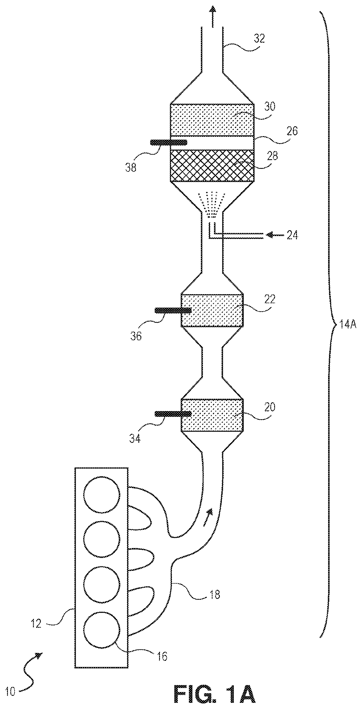
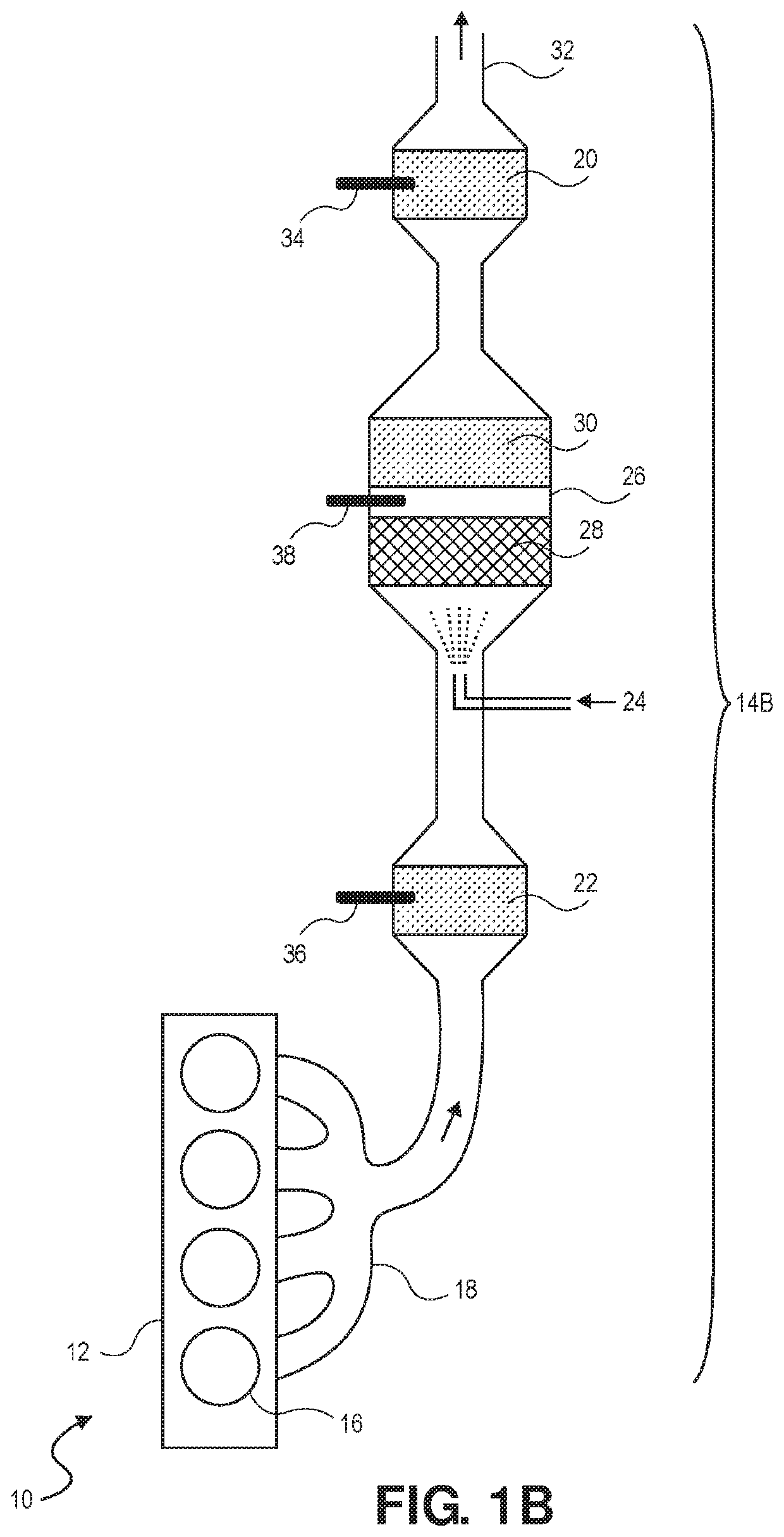
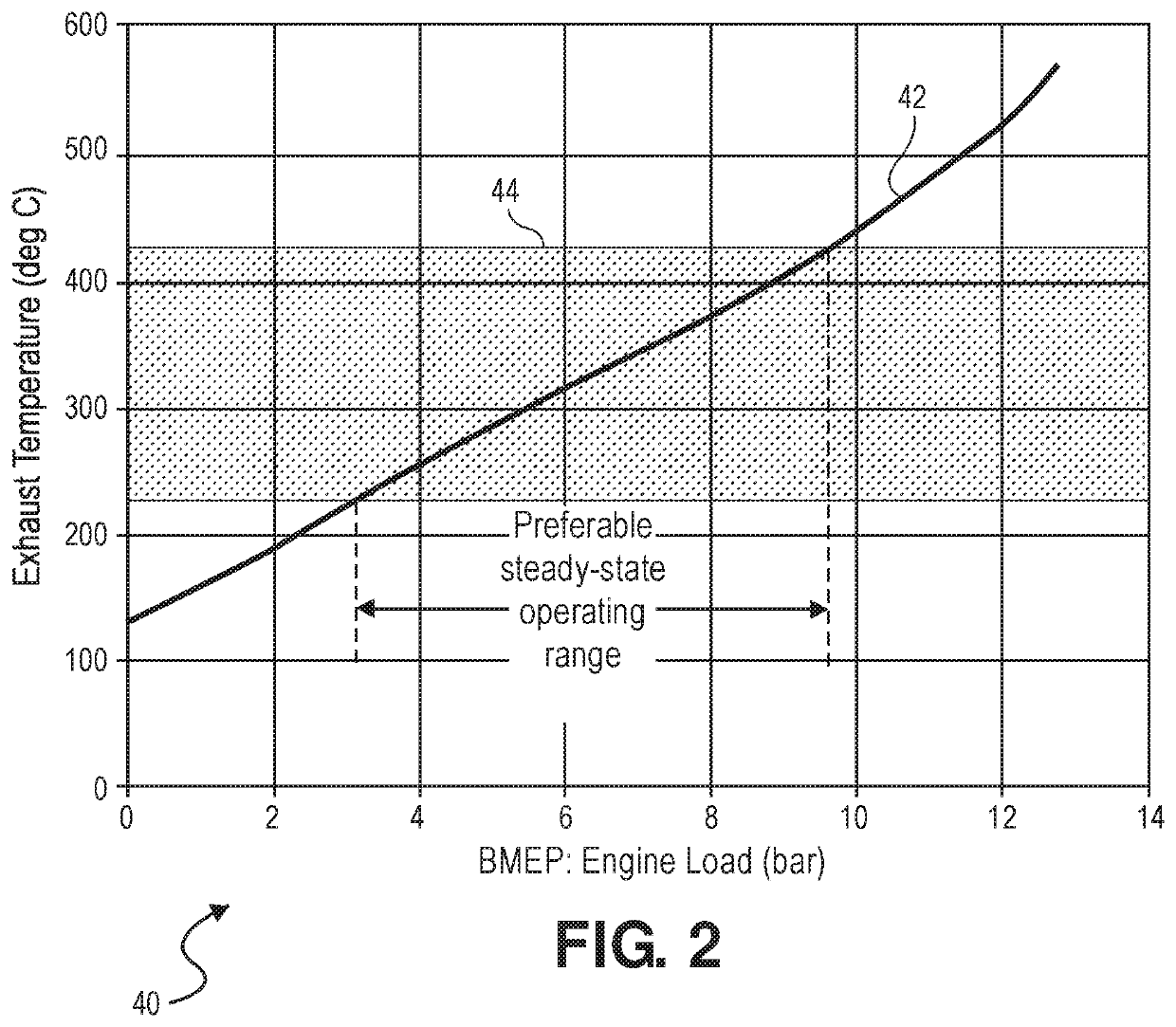
Firing density also impacts air flow through the engine, which may impact the efficacy of aftertreatment systems used to reduce tailpipe emissions.
Controlling the firing density through firing density transitions is also complicated by delays associated with adjusting the ratio of fresh air to recirculated exhaust gases in the intake manifold and the intake manifold pressure.

Method used


Image

  • Separately determining firing density and pumping density during firing density transitions for a lean-burn internal combustion engine
  • Separately determining firing density and pumping density during firing density transitions for a lean-burn internal combustion engine
  • Separately determining firing density and pumping density during firing density transitions for a lean-burn internal combustion engine

Examples


Embodiment Construction

[0048]The present invention relates to skip fire control that relies on a combination of a torque request, an exhaust temperature, an NVH level, and an air-fuel ratio in determining a firing density (FD) of an internal combustion engine. The internal combustion engine may be a lean burn engine and may be used to power a vehicle. In addition, the present invention also is directed to using different types of working chamber valve control during skipped firing opportunities that either allow or prevent pumping air through the engine to control and modulate exhaust gas temperature in aftertreatment systems.

Skip Fire Engine Control

[0049]Skip fire engine control contemplates selectively skipping the firing of certain cylinders during selected firing opportunities. Thus, for a given effective engine displacement that is less than the full displacement of the engine, a particular cylinder may be successively fired during one firing opportunity, skipped during the next firing opportunity an...


PUM


Abstract

A skip fire engine controller and method of control is described wherein during transitions from a first firing density to a second firing density, a firing density and a pumping density are separately set so as to balance the conflicting demands of (a) torque control, (b) Noise, Vibration and Harshness (NVH), (c) air flow through the engine and (d) air-fuel ratio.

Description

CROSS REFERENCE TO RELATED APPLICATIONS[0001]This application is a Continuation-in-Part of U.S. application Ser. No. 16 / 373,364 filed Apr. 2, 2019, which is a Continuation-in-Part of U.S. application Ser. No. 16 / 275,881, filed Feb. 14, 2019, which is a Continuation of U.S. application Ser. No. 15 / 347,562 (now U.S. Pat. No. 10,247,072, issued Apr. 2, 2019), filed on Nov. 9, 2016, which claims priority to U.S. Provisional Application No. 62 / 254,049, filed on Nov. 11, 2015. All the above listed applications are incorporated by reference herein in their entirety for all purposes.FIELD OF THE INVENTION[0002]The present invention relates to a skip fire engine control system for a lean burn internal combustion engine, and more specifically, to skip fire engine control wherein during transitions from a first firing density to a second firing density, a firing pattern and a pumping pattern are separately implemented so as to manage and balance the conflicting demands of (a) meeting the torqu...

Claims


Application Information

Patent Timeline
IPC IPC(8): F01N3/20F01N3/08F02D41/00F01N11/00F01N3/021F02D41/40F01N13/00
CPCY02T10/24F02D2041/0012F01N2900/1404F02D2200/0804F01N2900/1602F01N13/009Y02T10/44F01N3/2066F02D41/401F01N11/005F01N3/0814F01N3/021F02D2200/0802F01N2430/08Y02T10/47F01N3/2033F01N2900/08F02D41/0087F02D17/02F02D2250/18F02D2250/21Y02A50/20Y02T10/12Y02T10/40
Inventor CHEN, SHIKUI KEVINYOUNKINS, MATTHEW A.SERRANO, LOUIS J.
Owner TULA TECH INC
Learn More