
Bracket

a technology of brackets and supports, applied in the field of brackets, can solve the problem that the brackets require high stiffness to receive the load of the vehicle, and achieve the effect of avoiding damage to the fuel system component more reliably

Inactive Publication Date: 2020-01-23
HONDA MOTOR CO LTD
View PDF10 Cites 2 Cited by
  • Summary
  • Abstract
  • Description
  • Claims
  • Application Information

AI Technical Summary

Benefits of technology

The present patent describes a bracket structure that prevents fuel system components from colliding with vehicle body components during a collision. By using an inclined section in the bracket, the bracket can absorb the impact of the fuel system component and prevent damage to the fuel system. Additionally, the inclined section is designed to guide the vehicle body component upward and avoid contact with the fuel system component, reducing noise and vibration and improving overall safety.

Problems solved by technology

However, even in this case, the bracket requires high stiffness for receiving the load of the vehicle body component at the time of contact.

Method used


Image

  • Bracket
  • Bracket
  • Bracket

Examples


Embodiment Construction

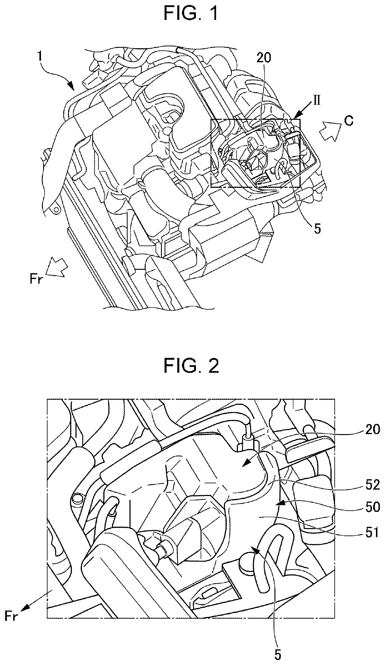
[0023]Hereinafter, a preferable embodiment of the present disclosure will be described with reference to the drawings. FIG. 1 is a perspective view, seen from a diagonally upper position, of an engine 1 which uses a bracket 5 according to an embodiment of the present disclosure.

[0024]FIG. 1 illustrates the manner in which various components, such as a high-pressure fuel pump 20, are mounted as fuel system components on the engine 1 for a vehicle. In the embodiment, an example will be described in which the engine 1 is disposed on a front Fr-side, and a vehicle cabin C is provided in back of the engine 1. Hereinafter, a description will be given under the assumption that the front, back, right, and left directions are referenced with respect to the front Fr of the vehicle as the front side for the sake of convenience.

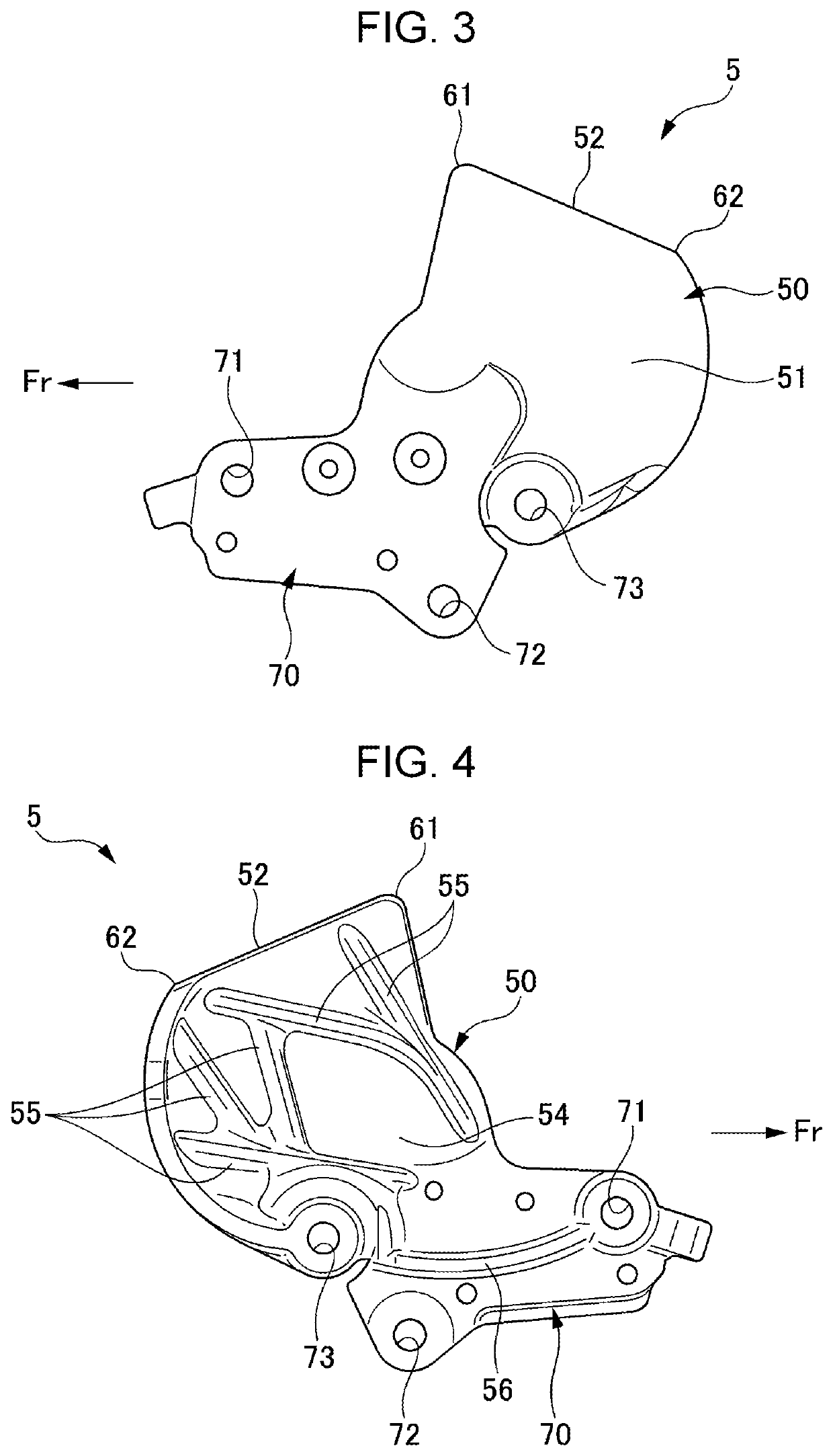
[0025]FIG. 2 is an enlarged perspective view illustrating a high-pressure fuel pump 20 as a fuel system component and a bracket 5 which are mounted on the engine 1. FIG....


PUM


Abstract

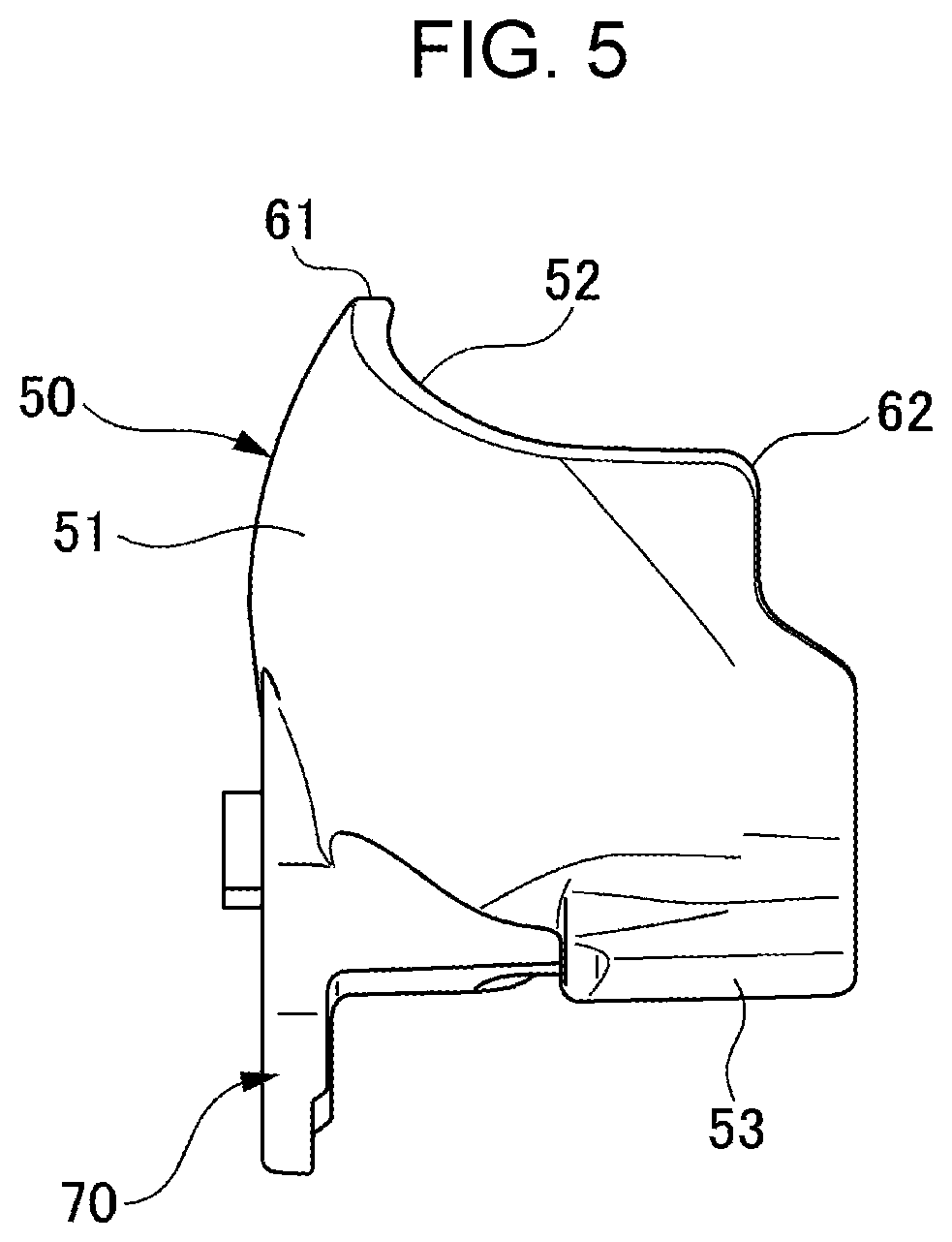
A bracket includes: a fastener fixed to an engine by a fastening member; and a protector that is disposed between a high-pressure fuel pump (fuel system component) and a vehicle body frame (vehicle body component) opposed to the high-pressure fuel pump, and covers the high-pressure fuel pump continuously from the fastener. The protector includes: an inclined section that is located more upward at a position further in a direction away from the vehicle body frame; and a curved surface section that is curved between the fastener and the inclined section.

Description

CROSS REFERENCES TO RELATED APPLICATIONS[0001]The present application claims priority under 35 U.S.C. § 119 to Japanese Patent Application No. 2018-134285, filed Jul. 17, 2018, entitled “Bracket.” The contents of this application are incorporated herein by reference in their entirety.BACKGROUND1. Field[0002]The present disclosure relates to a bracket that protects fuel system components.2. Description of the Related Art[0003]A conventional technique is known related to a bracket that protects a fuel system component, such as a high-pressure fuel pump which supplies fuel to an engine. This type of technique is described in, for example, Japanese Unexamined Patent Application Publication No. 2017-8769.[0004]Japanese Unexamined Patent Application Publication No. 2017-8769 relates to a protective structure for engine fuel supply system components for protecting the fuel supply system components mounted on the head cover of an engine by a protector. Japanese Unexamined Patent Application...

Claims


Application Information

Patent Timeline
IPC IPC(8): F02B77/08F02M37/00
CPCF02B77/08F02M37/0011F02M59/44F02M59/48
Inventor ICHIKAWA, AZUKITANAKA, SHUN
Owner HONDA MOTOR CO LTD
Learn More