Strain gauge sensor accelerometer with improved accuracy

a technology of accelerometer and gauge sensor, which is applied in the field of accelerometers, can solve the problems of loss of accuracy and increase in mass weight, and achieve the effects of improving accuracy, reducing the thickness of gauges, and facilitating fabrication processes

Active Publication Date: 2020-01-23
COMMISSARIAT A LENERGIE ATOMIQUE ET AUX ENERGIES ALTERNATIVES
View PDF0 Cites 0 Cited by
  • Summary
  • Abstract
  • Description
  • Claims
  • Application Information

AI Technical Summary

Benefits of technology

[0100]According to one particular embodiment, the second connection comprises a main coupling blade rigid with respect to the sensing axis and flexible with respect to the rotation axis. This enables transmission to the lever of in-plane movement or impact along at least one axis to be prevented.
[0101]According to one particular embodiment, the second connection further comprises at least one secondary coupling blade connected to the main coupling blade and perpendicular to said main coupling blade. This enables transmission to the lever of an in-plane movement or shock along both axes of the plane to be prevented.
[0102]The t

Problems solved by technology

The problem is that the weight of the mass is increased by increasing the size of the mass, and in the end of the accelerometer.
This leads to a risk, in the case of imperfect symmetry, that the mass will turn at the same time as one or the other of the two lever arms, the consequence of which is ag

Method used


Image

  • Strain gauge sensor accelerometer with improved accuracy
  • Strain gauge sensor accelerometer with improved accuracy
  • Strain gauge sensor accelerometer with improved accuracy

Examples


first embodiment

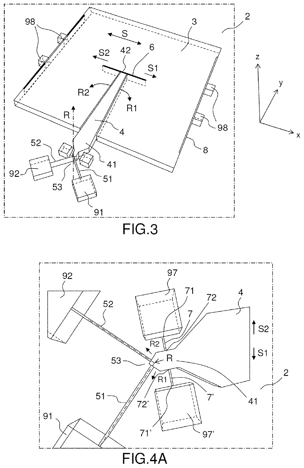
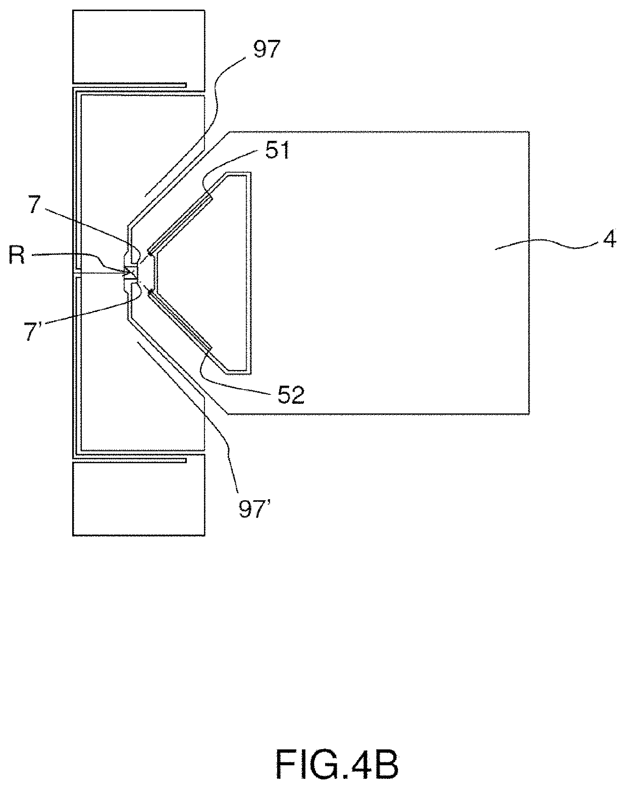
[0124]FIGS. 3, 4A, 4B, 5A, 5B, 6A and 6B show an accelerometer according to the invention which is an in-plane accelerometer.

[0125]An accelerometer is termed “in-plane” when the sensing axis on which the mobile mass moves is situated in a plane parallel to the substrate.

[0126]The accelerometer 1 according to the first embodiment includes a mass 3 intended to be moved by the effect of an external force, in this instance the effect of an acceleration along a sensing axis S situated in the plane of the substrate, here in the plane XY. The mass 3 is mobile in translation relative to the substrate 2 along the sensing axis S.

[0127]In the example shown, the sensing axis S is parallel to the axis X. They could coincide in the description of the first embodiment.

[0128]In the example shown, the mobile mass 3 is suspended over the substrate 2 by means of at least one third connection 8. An anchor pad 98 fixes a third connection 8 to the substrate 2. The third connection is optional.

[0129]In th...

second embodiment

[0180]FIGS. 7, 8A, 8B, 9, 10A and 10B show an accelerometer according to the invention, which is an out-of-plane accelerometer.

[0181]An accelerometer is termed “out-of-plane” when the axis sensing movement of the mobile mass is an axis perpendicular to the plane of the substrate.

[0182]The accelerometer 11 according to the second embodiment includes a mass 13 intended to be moved by the effect of an external force, in this instance by the effect of an acceleration perpendicular to the plane of the substrate 12 with respect to a sensing axis S. Here the plane of the substrate is the plane XY and the sensing axis S is parallel to the axis Z. The axis S and the axis Z may coincide in the remainder of the description of the second embodiment.

[0183]The mass 13 is mobile in translation relative to the substrate 12 in a movement in translation with respect to the sensing axis S.

[0184]The mobile mass 13 is suspended over the substrate 12 by means of at least one third connection 18. At least...


PUM


Abstract

An MEMS or NEMS accelerometer adapted to measure an acceleration along a sensing axis includes a substrate featuring a plane; a mass having a central zone and suspended relative to the substrate; a single lever arm comprising: a first end connected to the substrate by means of a first connection adapted to allow rotation of the lever arm about a rotation axis perpendicular to the sensing axis, and a second end connected to the mass by means of a second connection adapted to transmit movement in translation of the mass to the lever arm whilst allowing rotation of the lever arm about the rotation axis; the second end of the lever arm being disposed at the level of the central zone of the mass; at least one strain gauge comprising: a first end connected to the substrate, and a second end connected to the lever arm.

Description

CROSS-REFERENCE TO RELATED APPLICATIONS[0001]This application claims priority to foreign French patent application No. FR 18 56789, filed on Jul. 23, 2018, the disclosure of which is incorporated by reference in its entirety.FIELD OF THE INVENTION[0002]The invention is situated in the field of accelerometers, to be more precise NEMS or MEMS accelerometers, i.e. accelerometers produced by micromachining in a wafer of monolithic material, such as silicon, by means of collective fabrication technologies similar to those that are used in the fabrication of electronic integrated circuits.BACKGROUND[0003]Such accelerometers have multiple applications, in particular in fields where the aim is to obtain both a minimum overall size and a low production cost. One special field of application is the field of automotive or aeronautic navigation, in which these accelerometers enable a trajectory to be determined by integrating the signals that they supply.[0004]An accelerometer is expected to ha...

Claims


Application Information

Patent Timeline
IPC IPC(8): G01P15/12
CPCG01P15/123G01P2015/0877B81B3/0051B81B2201/0235G01P2015/0817G01P2015/0828
Inventor JOET, LOÏC
Owner COMMISSARIAT A LENERGIE ATOMIQUE ET AUX ENERGIES ALTERNATIVES
Why Eureka
Try Eureka