System, apparatus and method for dynamic carrier aggregation to multi-beam antenna mapping

a dynamic carrier and antenna mapping technology, applied in the field of radio access network telecommunications service technology, can solve the problems of ineffective use of sophisticated beamforming technologies, system architectures and solutions used for macro bts, and inapplicability to small-cell deployments, so as to eliminate or mitigate one or more disadvantages of known systems

Active Publication Date: 2020-01-23
BLINQ NETWORKS
View PDF0 Cites 10 Cited by
  • Summary
  • Abstract
  • Description
  • Claims
  • Application Information

AI Technical Summary

Benefits of technology

[0014]The present invention seeks to eliminate or mitigate one or more disadvantages of known systems, apparatus and methods using smart antenna technology and carrier aggregation, or at least provide an alternative.
[0018]In a further aspect, a multi-beam antenna system architecture is disclosed which can be configured to provide increased cell coverage and improved user experience, and is adaptable for any type of network morphology.
[0054]Thus, systems, apparatus and methods are disclosed herein provide for improving or optimizing the present small-cell architecture by providing capacity that can be dynamically steered, to create a configurable coverage pattern that will adapt to location in such way to increase coverage and lower interference. In particular, a simple antenna system is disclosed which comprises small form factor multiple directional antenna groups that can be configured as a function of location, which is fed by an RF switching apparatus that allows dynamic routing of multiple component carriers to one antenna group or multiple antenna groups.
[0055]Embodiments of the antenna system architecture, apparatus and methods are applicable specifically to an intra-band non-contiguous carrier aggregation use-case where multiple carriers cannot be aggregated over the same RF transceiver but can be aggregated over an antenna group. Therefore, apparatus and methods of embodiments described herein are configurable to aggregate any two or more channels (component carriers), each driven to a specific RF transceiver, and dynamically map them to different antennas with a low loss and high efficiency.
[0057]Thus, implementations of a multi-beam antenna system architecture, apparatus and methods are provided for dynamic carrier aggregation to multi-beam antenna mapping for improved capacity demand, using contiguous and non-contiguous component carriers. Embodiments are described which are particularly applicable to small-cell networks and have flexibility to adapt to any urban morphology, to improve or optimize cell coverage and user experience.

Problems solved by technology

Variability of capacity demand is one of the main challenges to be addressed in wireless cellular deployments.
The system architectures and solutions used for MACRO BTS may not be applicable to small-cell deployments for several reasons, e.g.: high costs, large form factor, high power consumption, active cooling, and in particular, deployment use-case.
For this reason, small-cell antenna patterns are highly influenced by the clutter and usage of sophisticated beamforming technologies is not very efficient.

Method used


Image

  • System, apparatus and method for dynamic carrier aggregation to multi-beam antenna mapping
  • System, apparatus and method for dynamic carrier aggregation to multi-beam antenna mapping
  • System, apparatus and method for dynamic carrier aggregation to multi-beam antenna mapping

Examples


Embodiment Construction

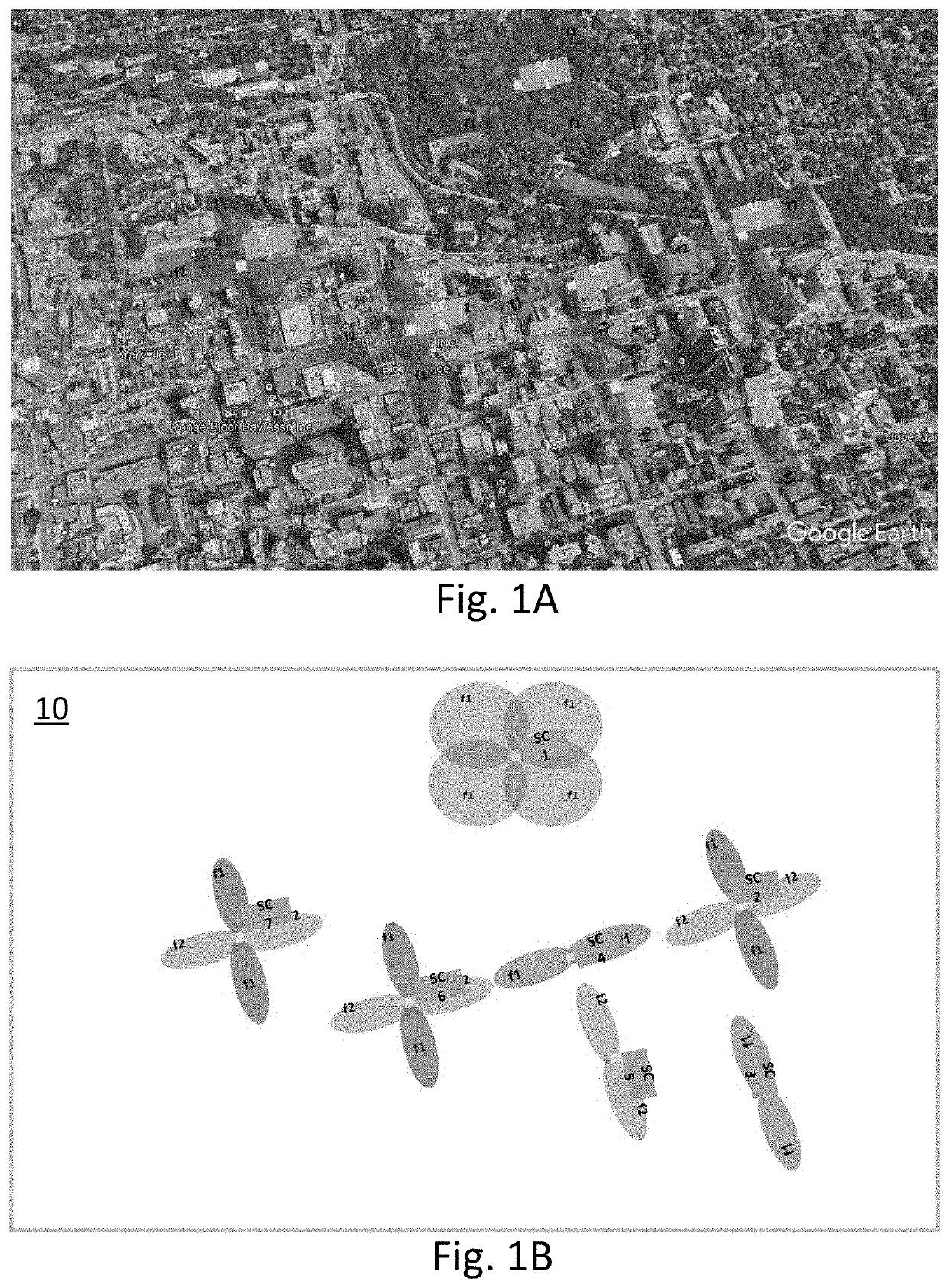
[0069]FIG. 1A shows a schematic diagram of a radio access network comprising a plurality of small-cells deployed in a dense urban environment, overlaid on an aerial map view of the downtown urban area which it serves, to illustrate some street level use-case scenarios for an urban network morphology. In this map area, there is a downtown area having a network of streets arranged in a rectangular grid pattern, i.e. streets running in generally east-west directions intersecting streets running in generally north-south directions, in which there are many high-rise buildings. The upper right part of the map area includes low-rise residential areas, a park area and non-linear street patterns. For clarity, FIG. 1B shows the same schematic overlay of FIG. 1A, with the underlying aerial map removed, to show the locations of 7 small-cell sites of the radio access network, and antenna patterns for each small-cell site.

[0070]In a typical dense urban environment, some of the small-cell (SC) sit...


PUM


Abstract

A multi-beam antenna system, apparatus and method for dynamic carrier aggregation to multi-beam antenna mapping in radio access networks, including small-cell deployments, is disclosed. Apparatus comprises a compact base transceiver unit with integrated multi-beam antenna comprising antenna groups configurable for operation in a plurality of modes, with one or more selected antenna groups enabled, for different use-case scenarios. The base transceiver unit comprises a daisy-chained radio-frequency (RF) system wherein one baseband processor feeds multiple RF transceivers; each RF transceiver front end comprises a software configurable isolation module through which each RF front end is interlinked to previous and next RF front ends to enable dynamic routing of TX / RX data streams through the daisy chain, e.g. routing a transmission data stream from any RF transceiver to any one of the antenna groups or multiple antenna groups, routing a received data stream from one or multiple antenna groups to any RF transceiver, and for contiguous or non-contiguous carrier aggregation.

Description

CROSS-REFERENCE TO RELATED APPLICATIONS[0001]This application claims priority from U.S. provisional patent application No. 62 / 699,531 filed Jul. 17, 2018, entitled “System, Apparatus and Method for Dynamic Carrier Aggregation to Multi-Beam Antenna Mapping”, which is incorporated by reference in its entirety.TECHNICAL FIELD[0002]The present invention relates generally to telecommunications service technology for radio access networks, and systems, apparatus and methods using smart antenna technology and carrier aggregation for improved network capacity.BACKGROUND[0003]Variability of capacity demand is one of the main challenges to be addressed in wireless cellular deployments. In both macro-cell and small-cell deployments, capacity demand may be variable by location and by time of day (ToD), or to accommodate planned or unplanned events.[0004]A macro-cell or macro-site is a large area cell in a mobile access network that provides radio coverage served by an outdoor high-power cell si...

Claims


Application Information

Patent Timeline
Patent Type & Authority Applications(United States)
IPC IPC(8): H04B7/06
CPCH04B7/0691H04L5/001H04B7/022H04L27/0002H01L2924/0002
Inventor LEULESCU, OVIDIU MIHAISELEA, RADU BOGDANNIYOMSATAYA, TERASAN
Owner BLINQ NETWORKS
Why Eureka
Try Eureka