Concrete pier foundation with lateral shear reinforcing loops and methods of constructing the same

a technology of lateral shear reinforcement and concrete piers, applied in the field of concrete foundations, can solve the problems of concrete foundations that are also subject to shear stress, premature failure, etc., and achieve the effect of increasing the lateral shear stress resistance of the foundation

Active Publication Date: 2020-01-30
TERRACON CONSULTANTS INC
View PDF0 Cites 5 Cited by
  • Summary
  • Abstract
  • Description
  • Claims
  • Application Information

AI Technical Summary

Benefits of technology

[0007]In view of the foregoing, the present invention is directed to a pier foundation having a plurality of elongated tower anchor bolts embedded within sleeves in a concrete pier and secured at their lower ends to an anchor or embedment ring to form a tower anchor bolt cage. The upper ends of the anchor bolts extend above the top of the concrete so that the bolts, which bear the tensile load...

Problems solved by technology

The '417 patent construction was a significant improvement over previously known concrete foundations that incorporated a reinforcing steel bar matrix and were subject to repeatedly alternating te...

Method used


Image

  • Concrete pier foundation with lateral shear reinforcing loops and methods of constructing the same
  • Concrete pier foundation with lateral shear reinforcing loops and methods of constructing the same
  • Concrete pier foundation with lateral shear reinforcing loops and methods of constructing the same

Examples


first embodiment

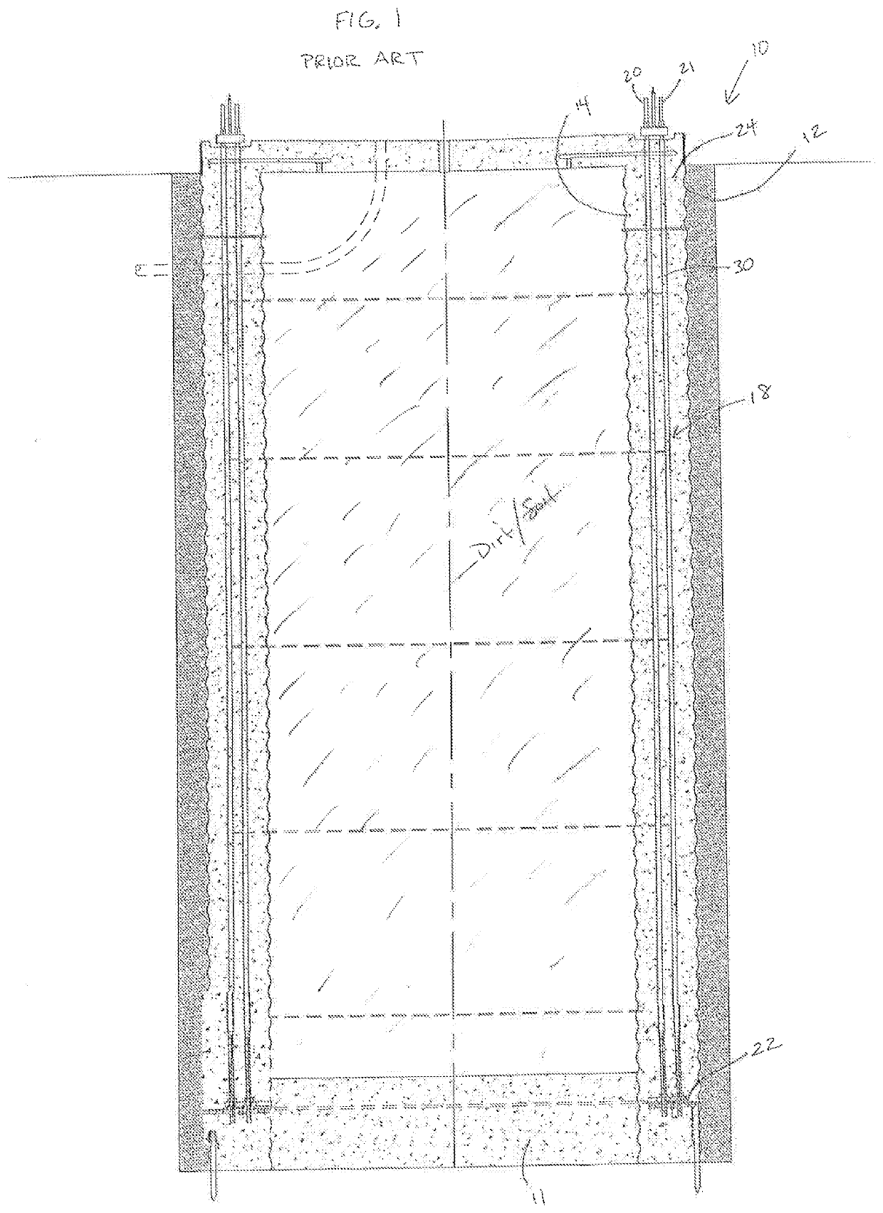
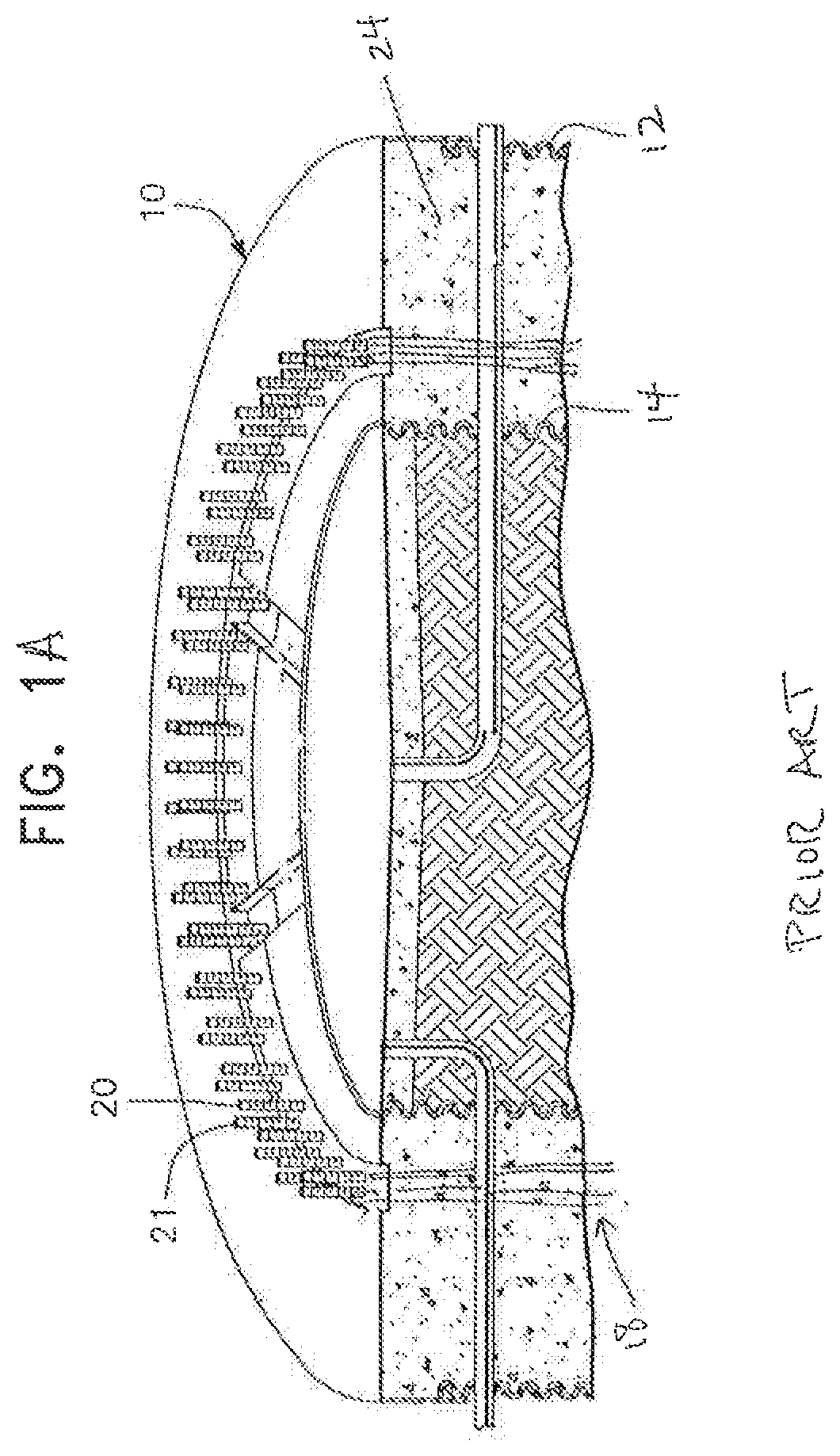
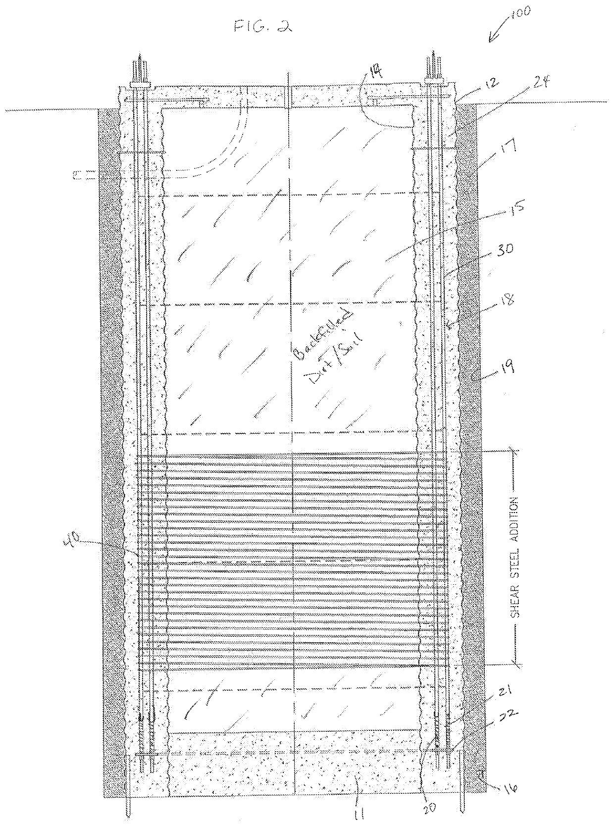
[0031] shown in FIG. 2, the present invention is directed to a pier foundation generally designated by reference numeral 100. As variously described in the '417 and '947 patents, the outer CMP 12 is initially placed within a hole or excavation formed in the ground and generally designated by reference numeral 16. The bolt cage 18 is installed vertically inside the outer CMP 12 with the anchor ring 22 at the bottom. The tower anchor bolts are nutted both atop and below the anchor ring to secure the anchor ring in place near the bottom of the foundation. The inner CMP 14 is then placed and positioned within the excavation 16 and the interior area 15 surrounded by the inner CMP 14 is partially backfilled along with the annular area 17 between the outer CMP 12 and the sidewall 19 of the excavation 16 to stabilize the CMPs generally in place within the excavation and relative to each other. Alternatively, a concrete plug 11 may be poured in the bottom of the inner CMP before backfilling ...

second embodiment

[0036]the present invention shown in FIG. 3 includes a pier foundation generally designated by reference numeral 200 having a spiral hoop encasement 140 that covers substantially the entire vertical extent of the pier foundation 200. As used herein, “substantially” is intended to cover spiral hoop encasements that cover at least 90% of the vertical extent, and preferably at least 95% of the vertical extent. The spiral hoop encasement 140 provides structural strength to the perimeter of the bolt cage 18 and eliminates the need for an outer CMP provided the surrounding sidewalls 19 of the excavation 16 are able to stand vertically when the hole for the foundation is drilled or excavated, such as in rock or stable soils.

[0037]The foundation 200 is constructed by drilling or excavating the hole 16, placing an inner CMP 14 and partly backfilling the center area 15 as necessary to stabilize the CMP 14. Alternatively, a concrete plug 11 may be poured to secure the inner CMP at the bottom. ...

third embodiment

[0038]the pier foundation with lateral shear reinforcing loops of the present invention is shown in FIG. 4 and generally designated by reference numeral 300. The foundation 300 is suitable for installation in areas having rock or stable soil where the side walls 19 of drilled or excavated deep holes stand vertically. With such conditions, the excavation is formed as an annular trench 310 which is bordered by sidewall 19 and an inner sidewall 190. The inner sidewall 190 defines the outer perimeter of a central area 115 which is constituted by the native soil which is not disturbed. With such a configuration, both the outer and inner CMPs are eliminated along with the need to backfill the inner CMP. In addition, the trench construction of FIG. 4 also eliminates the need to form a concrete plug at the base of the pier to secure the inner CMP.

[0039]The foundation 300 is constructed by excavating the trench 310, assembling the tower bolt cage 18 and wrapping the same with a spiral hoop e...


PUM


Abstract

A concrete pier foundation having a plurality of sleeved tower anchor bolts embedded therein and a spiral loop encasement providing lateral shear reinforcement is provided. The spiral loop encasement surrounds at least a lower portion of the concrete pier and is formed by hoop steel wrapped around the perimeter of the tower anchor bolt cage. In proper soils or rock the spiral loop encasement can eliminate the need for corrugated metal pipes, reducing the cost and complexity of construction.

Description

[0001]This application claims priority from U.S. provisional application Ser. No. 62 / 703,217, filed Jul. 25, 2018.BACKGROUND OF THE INVENTIONField of the Invention[0002]The present invention relates to concrete foundations used to support tall, heavy and / or large towers and the like, and to methods for the construction thereof.Description of the Related Art[0003]Concrete foundation structures of various kinds have been developed to support commercial signs, traffic signs, light poles and the like. To support larger structures including tall and heavy towers and wind turbines that exert significant overturning force on the foundation. Applicant developed and commercialized a tensionless pier foundation which is described in U.S. Pat. No. 5,586,417 (“the '417 patent”). The '417 patent is hereby expressly incorporated by reference as if fully set forth in its entirety herein.[0004]The tensionless pier foundation described in the '417 patent includes a concrete foundation formed as a cy...

Claims


Application Information

Patent Timeline
IPC IPC(8): E02D27/42E02D5/38
CPCE02D2300/002E02D5/38E02D2200/12E02D27/42
Inventor HENDERSON, ALLAN P.
Owner TERRACON CONSULTANTS INC
Why Eureka
Try Eureka