Caliper braking system for aircraft landing gear having a plurality of brake disk clamping zones

a technology of aircraft landing gear and brake disc, which is applied in the direction of brake discs, aircraft braking arrangements, mechanical devices, etc., can solve the problems of generating vibration in the brake(s), difficulty in installing in the aircraft landing gear, and the oscillation of the brake disc in the rim, so as to increase the number of brake disc clamping zones, increase the force, and facilitate the effect of installation

Active Publication Date: 2020-01-30
EUROCOPTER
View PDF0 Cites 2 Cited by
  • Summary
  • Abstract
  • Description
  • Claims
  • Application Information

AI Technical Summary

Benefits of technology

[0036]The brake disk is thus clamped by means of the pads firstly between the intermediate support and the outer support, and secondly between the inner support and the outer support. The braking system of the invention thus advantageously serves to multiply the number of brake disk clamping zones, while limiting the number of actuators that are needed.
[0037]The action of a single actuator thus enables a plurality of brake disk clamping zones to be obtained and serves advantageously to multiply the force that is generated by the actuator in order to obtain an amplified braking force. The force generated by the actuator, and consequently its dimensions, can therefore be limited compared with a prior art braking system, thereby making it easier to install in the aircraft landing gear.

Problems solved by technology

Furthermore, the force needed for braking is supplied by a single actuator, which therefore needs to be dimensioned accordingly, and which can be difficult to install in the aircraft landing gear.
In addition, the brake disk can oscillate in the rim and can generate vibration in the brake(s).
These phenomena tend to contribute to premature wear of the interface between the brake and the rim and / or to the appearance of vibration that is audible, and / or to fatigue stresses.

Method used


Image

  • Caliper braking system for aircraft landing gear having a plurality of brake disk clamping zones
  • Caliper braking system for aircraft landing gear having a plurality of brake disk clamping zones
  • Caliper braking system for aircraft landing gear having a plurality of brake disk clamping zones

Examples


third embodiment

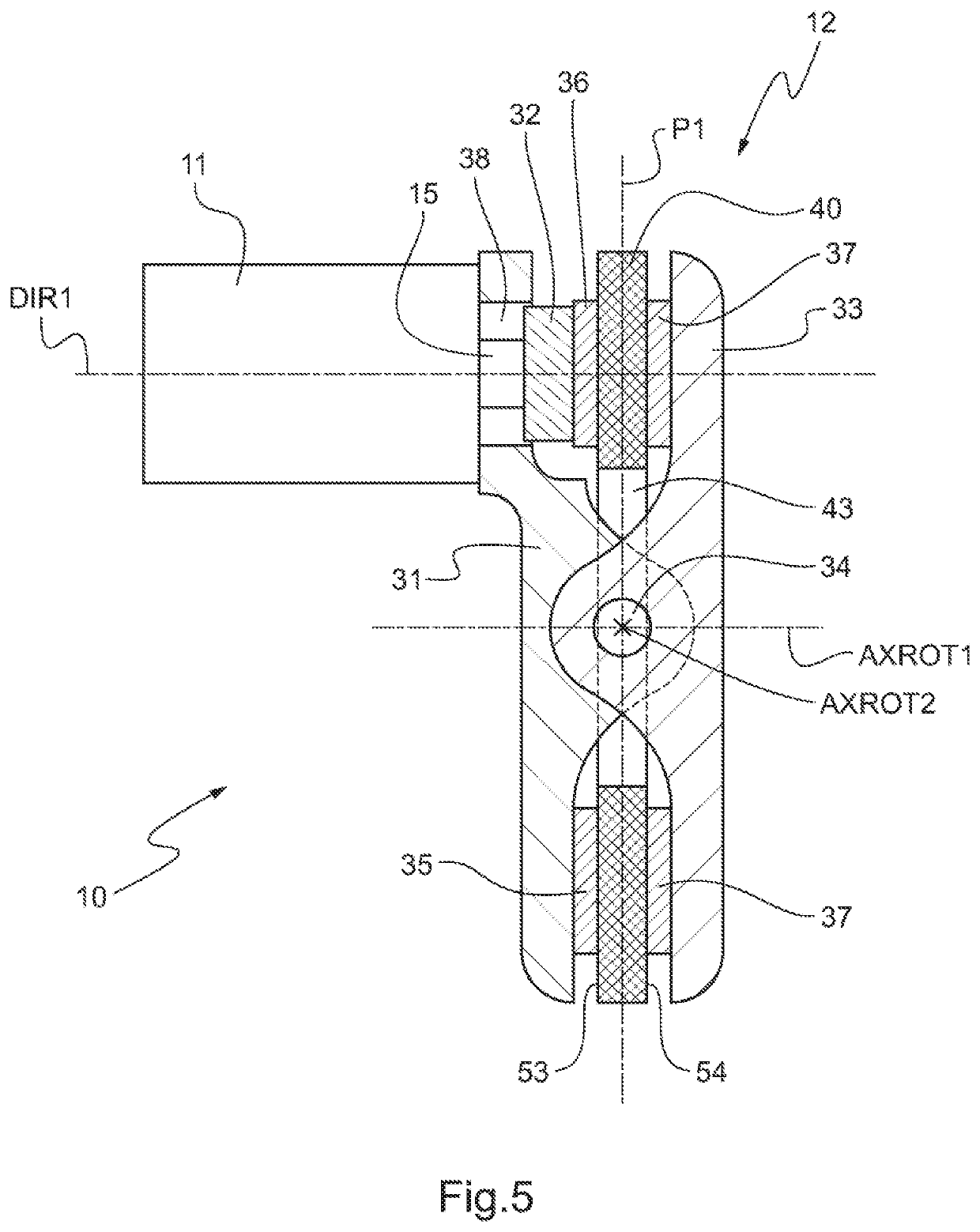
[0068]In the braking system 10, the pivot axis AXROT2 is arranged so as to be offset firstly from the midplane P1 of the brake disk 40 parallel to the axis of rotation AXROT1, and secondly relative to the axis of rotation AXROT1 in a direction perpendicular to the axis of rotation AXROT1 and to the pivot axis AXROT2.

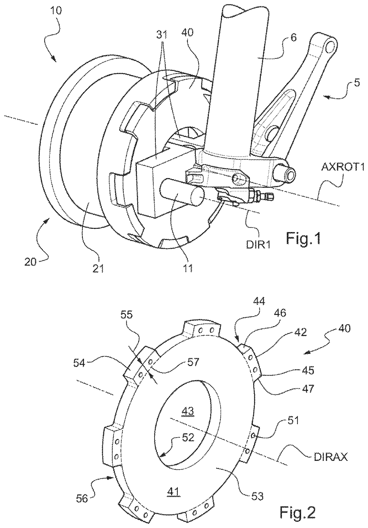
[0069]Advantageously, the caliper 12 of the braking system 10 thus includes at least one zone for clamping the brake disk 40 on either side of the pivot axis AXROT2. For each clamping zone, two supports 31, 32, 33 situated on either side of the brake disk 40 carry respective pads 35, 36, 37.

first embodiment

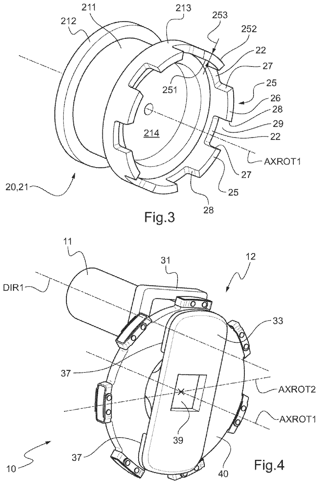
[0070]In the first embodiment, the intermediate support 32 co-operates with the outer support 33 to form a first zone for clamping the brake disk 40, while the inner support 31 co-operates with the outer support 33 to form a second clamping zone. The inner support 31 and the intermediate support 32 then carry respective single pads 35, 36, while the outer support 33 carries two pads 37. These two clamping zones may be of identical dimensions, as shown in FIG. 4.

[0071]In the second and third embodiments, the intermediate support 32 co-operates with the outer support 33 in order to form a first zone for clamping the brake disk 40, whereas the inner support 31 co-operates with the outer support 33 in order to form both a second clamping zone and a third clamping zone. The inner support 31 thus has two pads 35, the intermediate support 32 thus has a single pad 36, and the outer support 33 has three pads 37. In the second embodiment, these three clamping zones are of identical dimensions...


PUM


Abstract

A braking system for aircraft landing gear including a plurality of clamping zones for clamping a brake disk. The braking system comprises an actuator, a caliper, a rim rotatable about an axis of rotation, and the brake disk, which is floatingly mounted relative to the rim. The caliper comprises a stationary inner support, a movable intermediate support, and an outer support that is hinged relative to the inner support. Under action of the actuator, the movable intermediate support moves and causes the brake disk to move so that the brake disk is clamped between the intermediate support and the outer support, and then causes the outer support to tilt so that the brake disk is damped between the inner support and the outer support.

Description

CROSS-REFERENCE TO RELATED APPLICATION'S[0001]This application claims priority to French patent application No. FR 1800600 filed on Jun. 12, 2018, the disclosure of which is incorporated in its entirety by reference herein.BACKGROUND OF THE INVENTION(1) Field of the Invention[0002]The present invention relates to a caliper braking system for wheeled aircraft landing gear, the system having a plurality of brake disk clamping zones, and the invention also relates to wheeled landing gear including such a braking system and to an aircraft including such a braking system.(2) Description of Related Art[0003]A known braking system for aircraft comprises at least one brake and a brake disk floatingly mounted relative to a rim carrying a tire. Each brake is configured to brake the brake disk and consequently the rim. Conventionally, a brake comprises an actuator acting on brake pads in order to clamp the brake disk by means of said brake pads. The actuator is generally hydraulic.[0004]The te...

Claims


Application Information

Patent Timeline
Patent Type & Authority Applications(United States)
IPC IPC(8): F16D65/12B64C25/44F16D65/00
CPCB64C25/44F16D65/121F16D65/0075F16D65/123F16D55/2245F16D55/31F16D2055/005F16D2125/64
Inventor PRUD'HOMME LACROIX, PIERREBISTUER, OLIVIER
Owner EUROCOPTER
Why Eureka
Try Eureka