Pipe and universal coupling for supplying instruments for dental or surgical use

a technology for dental or surgical use and pipe, applied in the field of supply pipes, can solve the problems of difficult use reliably, risk for patients, and almost impossible installation of additional connectors in such couplings, and achieve the effect of increasing the number of electrical connections

Active Publication Date: 2013-08-27
BIEN AIR HLDG SA
View PDF9 Cites 1 Cited by
  • Summary
  • Abstract
  • Description
  • Claims
  • Application Information

AI Technical Summary

Benefits of technology

[0008]The present invention concerns an arrangement of a supply pipe, in particular of its universal coupling, which increases the number of electrical connections in order to offer other possibilities of combining supply or control lines and conduits and which thus allows new types of dental or surgical instruments to be connected as required, without necessarily changing the usual arrangement of the connectors in the universal coupling or the dimensions of the latter.
[0010]Thus, the invention not only actually increases the number of electric connections available while preserving the arrangement and size of the universal coupling, but it also multiplies the number of different arrangements of connectors in the couplings to be connected to the universal coupling, in particular the couplings belonging to the various instruments that one could envisage supplying via the pipe and the associated unit.

Problems solved by technology

However, this standardization has a drawback in certain cases, because it becomes almost impossible to install additional connectors in such a coupling, since virtually all of the available places on the front face are occupied by the usual connectors.
A typical example of such an additional connection is the earthing (grounding) of certain apparatus or instruments whose electric circuits could pose a risk for a patient.
This arrangement appears to be difficult to use reliably, if one considers that at least one of the two electric lines would have to be well insulated over its entire length with respect to the external medium and the water contained in the pipe.

Method used


Image

  • Pipe and universal coupling for supplying instruments for dental or surgical use
  • Pipe and universal coupling for supplying instruments for dental or surgical use
  • Pipe and universal coupling for supplying instruments for dental or surgical use

Examples


Embodiment Construction

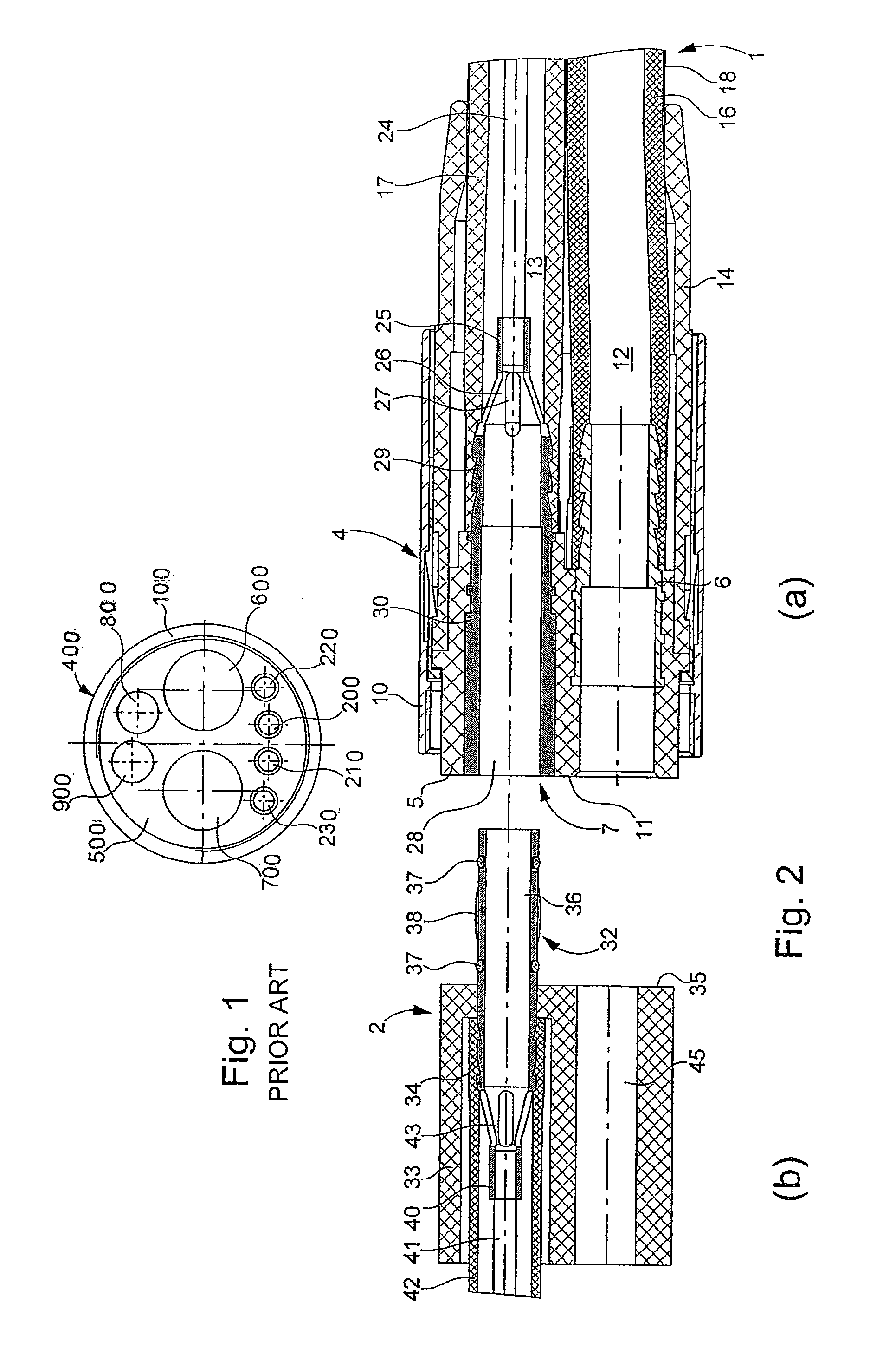
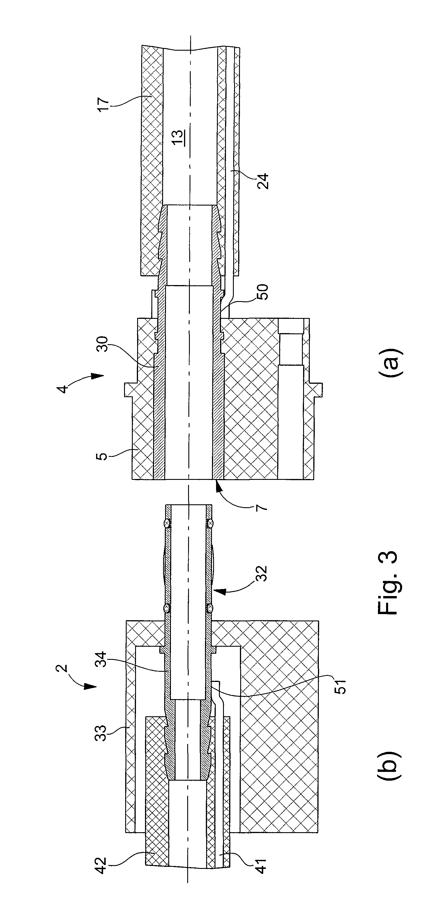
[0022]A first embodiment will be described by way of example with reference to FIG. 2, one part (a) of which shows a universal coupling 4 mounted at the front end of a supply pipe 1 from a supply and control unit, whereas part (b) shows schematically one part of a back coupling 2 arranged to be coupled with coupling 4. The back coupling 2 can form part of an intermediate part or a handpiece, or even another apparatus supplied and / or controlled via pipe 1, for example, an apparatus including an electric motor or an air turbine.

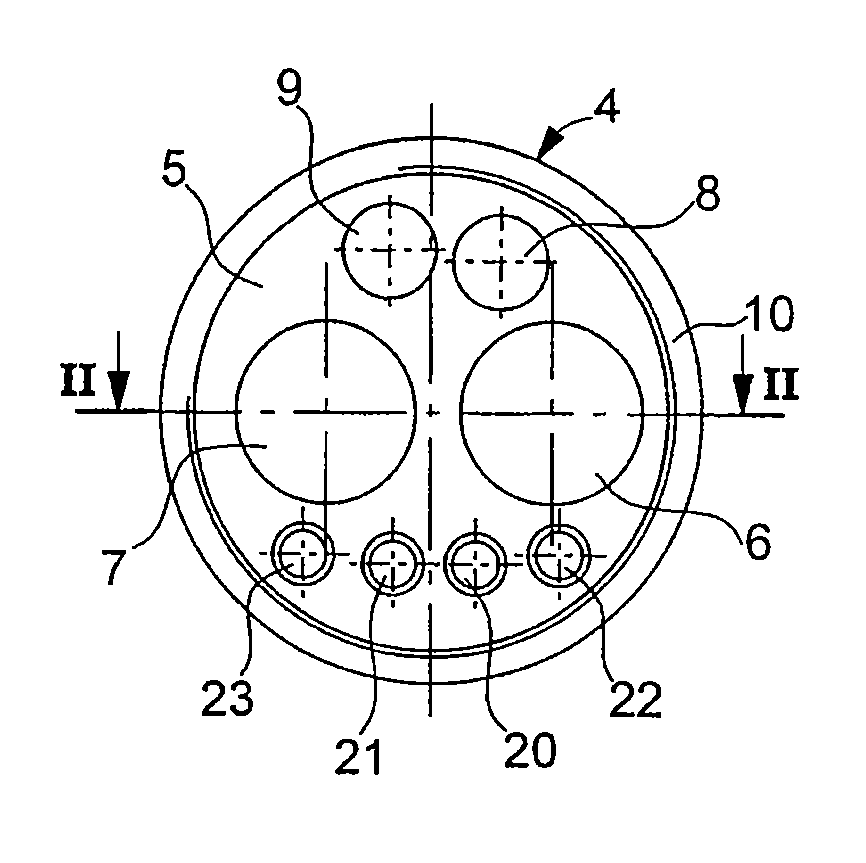
[0023]Coupling 4 of FIGS. 2 and 6 of the present application is similar to that of FIG. 1 (FIG. 2 of CH Patent No. 676 081) described above, but altered in many ways by the addition of an additional electric line, in this case an earth line (i.e., a ground). FIGS. 2 and 6 of the present application show a body 5 made of insulating synthetic material, containing in particular the female connector 6 for a pressurized air conduit 12 and the female connector 7 for ...


PUM


Abstract

A supply pipe for connecting an instrument for dental or surgical use to a control and supply unit contains fluid conduits and electric lines and includes at a front end a universal coupling for connecting different types of the instrument in a removable manner to part or all of the conduits and lines. The universal coupling includes fluid connectors coupled to conduits and electric connectors coupled to lines, wherein each of the connectors occupies a place on a front face of the universal coupling. The supply pipe contains at least one additional electric line including an additional conductor which is not coupled to one of the electric connectors, but to one of the fluid connectors of the universal coupling, wherein the dual function connector is arranged to provide a choice between a fluid connection, an electric connection or both.

Description

[0001]This is a National Phase Application in the United States of International Patent Application No. PCT / EP2005 / 004987 filed May 9, 2005, which claims priority on European Patent Application No. 04012687.2, filed May 28, 2004. The entire disclosures of the above patent applications are hereby incorporated by reference.FIELD OF THE INVENTION[0002]The present invention concerns a supply pipe for connecting an instrument for dental or surgical use to a control and supply unit, wherein the pipe contains fluid conduits and electrical lines and comprises at a front end a universal coupling for connecting different types of the instrument to a part of or to all of the conduits and lines in a removable manner, the universal coupling comprising fluid connectors coupled to the conduits and electrical connectors connected to the lines, each of the connectors occupying a place on a front face of the universal coupling.BACKGROUND OF THE INVENTION[0003]Pipes and adapters of this type are well ...

Claims


Application Information

Patent Timeline
Patent Type & Authority Patents(United States)
IPC IPC(8): A61C1/08A61B17/00A61B17/16A61C1/05A61C1/18F16L11/12
CPCA61B17/1628A61C1/052A61C1/18A61B2017/00477
Inventor MOSIMANN, VINCENT
Owner BIEN AIR HLDG SA
Why Eureka
Try Eureka