Concrete structure manufacturing apparatus and method

a manufacturing apparatus and concrete technology, applied in the direction of spray nozzles, auxillary shaping apparatus, feeding arrangments, etc., can solve the problems of weak cohesion between layers, thin layers of fine mortar on top of each other, and concrete elements that cannot integrate reinforcement, etc., to achieve the effect of easy integration of reinforcemen

Pending Publication Date: 2022-02-24
MOBBOT SA
View PDF0 Cites 0 Cited by
  • Summary
  • Abstract
  • Description
  • Claims
  • Application Information

AI Technical Summary

Benefits of technology

[0017]According to a preferred embodiment of the present invention, the concrete elements manufacturing apparatus further comprises a scarping element which is positioned at the rear of the projection head and parallel to its advancement direction. In this manner, one can adapt the height of each layer to be even. It can also comprise a second scraping element which is perpendicular to the advancement direction so as to smooth the surface between the layers.
[0021]Advantageously, the guiding surface is coated with a slippery liquid-infused porous surface (SLIPS). In this manner, the sprayed concrete does not stick to the surface of the surfaces and provide an even more smooth and dense lateral surface to the concrete layer. Advantageously, the guiding surface is mounted on a system that allow them to rotate. According to a preferred embodiment of the present invention, the guiding surface is pivotably mounted to as be able to pivot along a vertical axis and / or a horizontal axis. In this manner, the projection head can create curved walls.
[0022]Preferably, the guiding surfaces are movable with respect to each other so as to be able to vary the distance and / or the position between them and / or with respect to the projection nozzle. Thus, the projection head can vary the thickness of the generated wall. The two guiding surfaces can also move on in a lateral movement to each other allowing to cope with complex shapes.
[0024]Advantageously, the concrete elements manufacturing apparatus further comprises rollers disposed in front of the surface. In this manner, the projection head is more stably moved.
[0026]The concrete elements manufacturing apparatus further preferably comprises a quality control system which can comprise at least one specific sensor verifying the consistency of the concrete at different levels of said apparatus. In this manner, a user can continuously control the type of concrete which is used.
[0032]According to a preferred embodiment of the present invention, the method further comprises integrating a passive reinforcement made out of steel rebars and / or glass fibers of carbon mesh into said manufactured wall by providing it along the projection head path such that the projection head projects and surrounds the concrete material on it. In this manner, one can multiply the number of types of walls created and easily integrate reinforcement into the walls.

Problems solved by technology

The main disadvantage of contour crafting is that only thin layers of a fine mortar are added on top of each other as explained in the document US 2005 / 196484 A1.
The cohesion between the layers is weak and produced concrete elements does not allow to integrate reinforcement and must be filled later with concrete.
The fine grain of the material does not suit to structural applications and the surface textures is uneven and this is a serious issue for the customers.
The method is slow, requires special design of the reinforcement, and a second manufacturing step to smoothen the surface of the concrete poured between the reinforcement parts.
The resulting sprayed concrete surface is uneven.
The main drawback is that with this apparatus and this method, the lateral surfaces of the resulting manufactured concrete elements have a rough surface and a completely irregular shape from one layer to the other one and even within the same layer thereby providing a completely irregular surface.
Because of this, additional steps are required for smoothening the concrete surface using a tool to cut the surface or smoothen the surface and the designed structure therefore causing a waste of time and money

Method used


Image

  • Concrete structure manufacturing apparatus and method
  • Concrete structure manufacturing apparatus and method
  • Concrete structure manufacturing apparatus and method

Examples


example 1

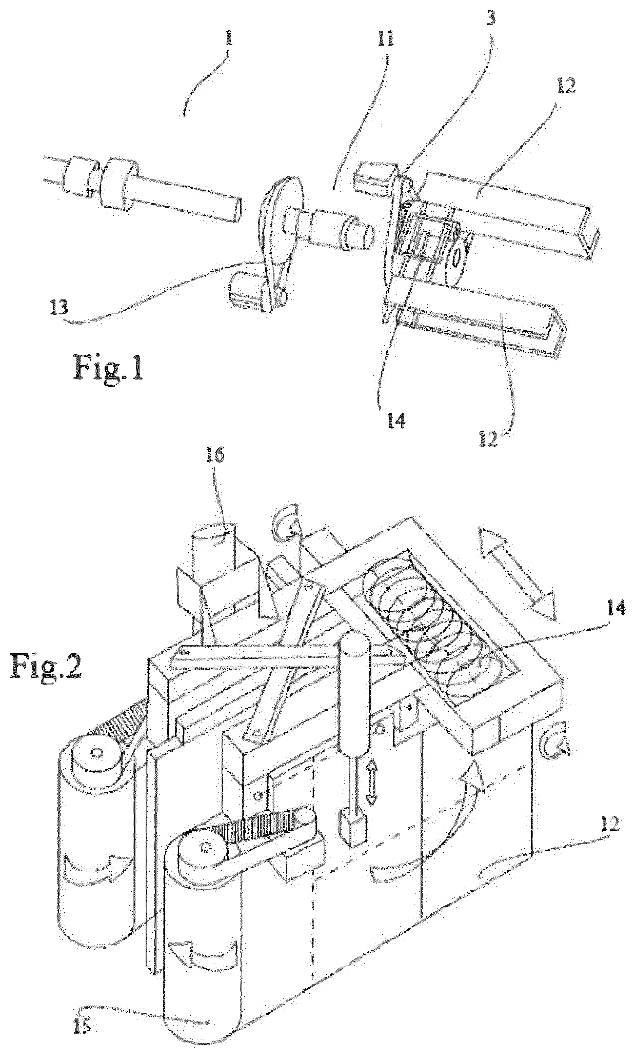
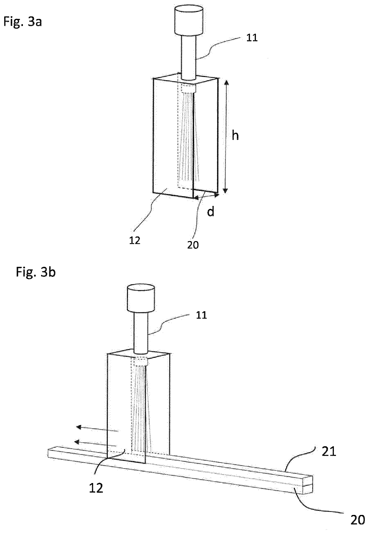
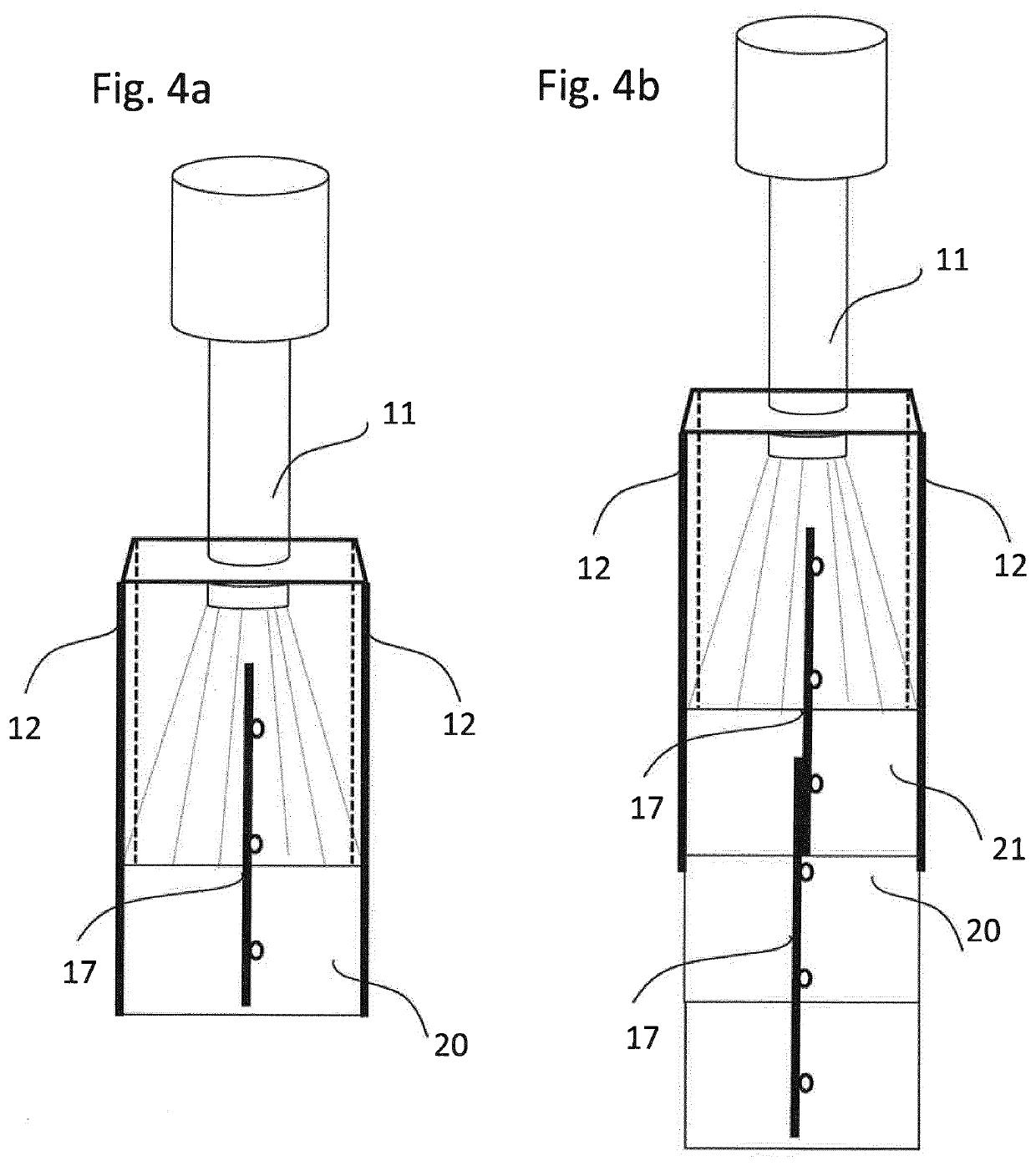
[0069]We use a concrete flow rate of 90 Kg / min, an air flow of 4 m3 / min, an air pressure of 7 bar. The rheology of the concrete has been measured with a small steal cone of 5×10×15 cm and the resulting flow was of 13 cm. The height of the guiding plates 12 between the projection nozzle 11 and the bottom layer of concrete is comprised between 24 and 36 cm and the distance between the two guiding plates 12 is 8.5 cm. We varied the robot speed between 10 and 20 cm / sec with an optimum at around 18 cm / sec

[0070]The resulting object showed very satisfying lateral side smoothness and layer to layer adhesiveness.

example 2

[0071]We use a concrete flow rate of 95-110 Kg / min, an air flow of 6 m3 / min, and an air pressure of 7.5 bar. The height of the guiding plates 12 between the projection nozzle 11 and the bottom layer of concrete is comprised between 36 and 100 cm and the distance between the two guiding plates 12 varies between 14 to 20 cm. We varied the robot speed between 5 and 15 cm / sec[0072]The resulting object showed very satisfying lateral side smoothness and layer to layer adhesiveness.

[0073]While the embodiments have been described in conjunction with a number of embodiments, it is evident that many alternatives, modifications and variations would be or are apparent to those of ordinary skill in the applicable arts. Accordingly, this disclosure is intended to embrace all such alternatives, modifications, equivalents and variations that are within the scope of this disclosure. This is for example particularly the case regarding the different concretes or additives which can be used, or the dif...


PUM

PropertyMeasurementUnit
heightaaaaaaaaaa
heightaaaaaaaaaa
distanceaaaaaaaaaa

Abstract

The present relates to an apparatus for manufacturing 3-dimensional concrete structures comprising a projection head (1) for spraying concrete material, wherein the projection head (1) comprises a projection nozzle (11) for spraying the concrete material and at least two guiding surfaces (12) provided on both sides of the projection nozzle (11) and defining a volume in between, such that the projection nozzle (11) is adapted to spray the concrete material into said volume, and wherein the projection head (1) is repeatedly moved along a predefined path by a control means and is configured to adjust the position of the two guiding surfaces (12) during the movement of the projection nozzle (11) so as to create a 3-dimensional concrete structure made of a plurality of projected concrete layers.

Description

TECHNICAL FIELD[0001]The present invention relates to an apparatus for fabricating a 3-dimensional concrete structure, a reinforced 3-dimensional concrete structure and a method of fabrication the same. More particularly, it relates to an additive manufacturing method and apparatus of concrete structure for producing 3-dimensional concrete structures and combining spraying techniques, molding techniques with functional concrete surface.BACKGROUND OF THE ART[0002]Additive manufacturing of concrete exists since the 80'. There are four types of additives manufacturing of concrete, the contour crafting method which is the most widely used method, the smart dynamic casting, mesh mold techniques and the conventional high speed sprayed concrete.[0003]As its name suggests, the contour crafting method extrudes mortar filaments (fine materials <4 mm) in successive thin layers and typically limited in height from few mm to 2-4 cm. This additive manufacturing creates hollow pieces, with more...

Claims


Application Information

Patent Timeline
Patent Type & Authority Applications(United States)
IPC IPC(8): B28B1/00B05B1/28B28B13/02B28B17/00B33Y10/00B33Y30/00B33Y50/02E04G21/04
CPCB28B1/001B05B1/28B28B13/021B28B17/0081E04B1/16B33Y30/00B33Y50/02E04G21/04B33Y10/00E04G21/0436E04G21/0463E04G2021/049B05B7/149
Inventor PETIT, AGNÉSSTUCKI, WILLIAMLULLIN, SIMONGALÉ, BENJAMINZULIANI, FABIO
Owner MOBBOT SA
Why Eureka
Try Eureka