
Optimized capturing window in a distance measuring system

Inactive Publication Date: 2020-01-30
SONY MOBILE COMM INC
View PDF0 Cites 0 Cited by
  • Summary
  • Abstract
  • Description
  • Claims
  • Application Information

AI Technical Summary

Benefits of technology

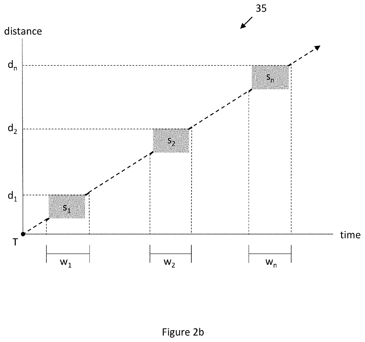
The distance measuring system described in this patent uses a receiving device to estimate the distance between it and a transmitting device by measuring the time it takes for a signal to travel from the transmitting device to the receiving device. This estimate is then used to set an optimized capturing window for the receiving device. This optimized capturing window helps to capture only the data that is relevant to the distance measurement, reducing the amount of unnecessary data and saving memory and power consumption. The optimized capturing window can be set by determining a start time and duration or by setting both a start and end time. Overall, this technology improves the accuracy and efficiency of distance measuring systems.

Problems solved by technology

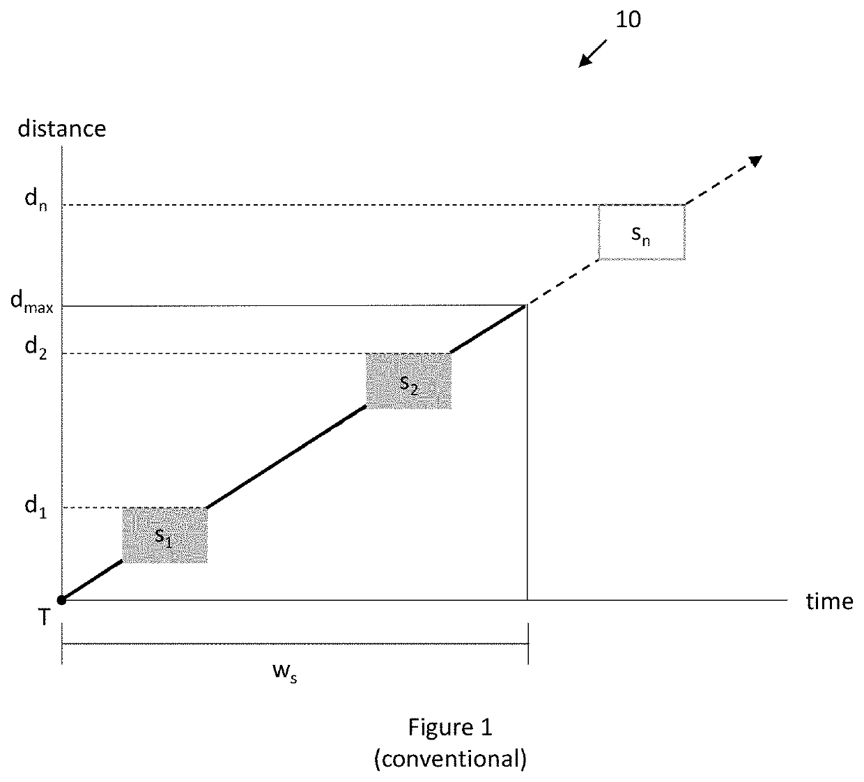
Not only are time and distance limitations created by ws, but the use of ws in a conventional distance measuring system also results in the capturing of irrelevant data, represented by the bolded line, that does not include the transmitted US signal before the receiving device receives the transmitted US signal and after the transmitted US signal has passed the receiving device.
This not only uses an unnecessary amount of memory, but consumes an unnecessary amount of power to process the irrelevant data.
There also exists a risk of capturing reflections of the US signal, which may lead to complications in the resulting distance calculation.
Even in this scenario, however, substantial irrelevant data not including the transmitted US signal will still be captured in the time between receipt of the RF signal and receipt of the US signal and after the US signal has passed.

Method used


Image

  • Optimized capturing window in a distance measuring system
  • Optimized capturing window in a distance measuring system
  • Optimized capturing window in a distance measuring system

Examples


Embodiment Construction

[0053]Embodiments of the present invention will now be described with reference to the drawings, wherein like reference numerals are used to refer to like elements throughout. It will be understood that the figures are not necessarily to scale.

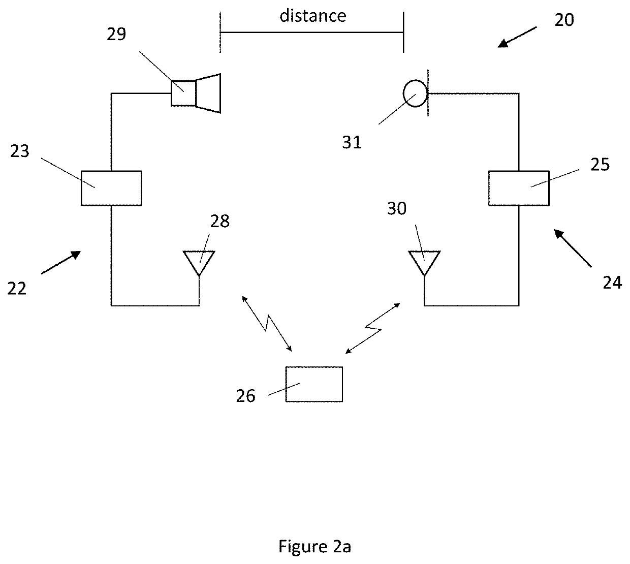
[0054]With reference to FIG. 2a, an exemplary distance measuring system 20 is depicted. The distance measuring system 20 comprises a first device 22, also referred to herein as a transmitting device, configured to transmit an electromagnetic signal and a sound signal. The transmitting device 22 may be configured to transmit the electromagnetic signal and the sound signal substantially at the same time. For example, due to typical delays, such as group delay and antenna delay in the transmitting device 22, as well as other unknown delays in the distance measuring system 20, a minor discrepancy in the relative timing of transmission of the electromagnetic and sound signals may result. This minor discrepancy may thereafter be accounted for as an ...


PUM


Abstract

A second device for measuring a distance from a first device is provided. The second device includes an electromagnetic receiver configured to receive an electromagnetic signal transmitted by the first device at a first time and a sound receiver configured to receive a sound signal transmitted by the first device at a second time. The electromagnetic signal and the sound signal are transmitted substantially at the same time. The second device also includes a processor configured to approximate the distance of the second device from the first device based on the first time, set a capturing window for capturing the sound signal based on the approximated distance and capture the sound signal within the set capturing window. The processor is configured to determine the distance of the second device from the first device based on the first time and the captured sound signal.

Description

FIELD OF INVENTION[0001]The present invention relates generally to distance measuring systems, and more particularly to a distance measuring system with an optimized capturing window.BACKGROUND OF THE INVENTION[0002]Cricket is an indoor location or distance measuring system that uses a combination of radio frequency (RF) and ultrasound (US) technologies to provide location information, such as space identifiers, position coordinates, and orientation of objects to a host device. Cricket systems use two types of devices, including listeners and beacons, each having an RF transceiver, a microcontroller, and other associated hardware for generating and receiving RF and US signals and interfacing with the host device.[0003]Objects to be monitored are equipped with listeners, also referred to herein as receiving devices, configured to receive RF and US signals transmitted by various beacons, also referred to herein as transmitting devices, placed throughout an indoor area as fixed referen...

Claims


Application Information

Patent Timeline
IPC IPC(8): G01S11/16
CPCG01S11/16
Inventor FALK, MATTIASFÄNGE, THOMASBERGKVIST, HANNESBERGKVIST, IVAR
Owner SONY MOBILE COMM INC
Learn More