
System and method for target detection

Inactive Publication Date: 2020-02-06
BUSH SHANE
View PDF23 Cites 0 Cited by
  • Summary
  • Abstract
  • Description
  • Claims
  • Application Information

AI Technical Summary

Benefits of technology

The present invention is a system that enhances the customer experience of golfers by modifying their golf targets or installing new ones through the use of vibration sensors. These sensors are placed in the target to detect the vibrations caused when a golf ball hits it. The vibration sensor array is designed to be attached to purpose-made or pre-existing targets, making it easy to standardize and install. The system provides instant feedback, allowing players and spectators to quickly see the results of their shots. The sensor array is small and lightweight, making attachment methods easy. Overall, this invention provides golfers with a more immersive experience and improved learning opportunities.

Problems solved by technology

One of the reasons for the decreased popularity of golf, especially amongst the millennials, is the time it takes to play an 18-hole golf course (approximately four hours) and the lack of mass social interaction afforded players.
The decreasing in popularity of the game of golf is a problem that remains largely unsolved.
Typically, they present an inferior alternative to the game of golf.
Specifically, while players can use driving ranges at any time of the day and there is no specific time-commitment, these facilities typically do not offer the environment of a competitive game and typically do not offer mass social interaction.
These facilities are few and available locations are limited.
In a generally declining market, however, operators are reluctant to make large investments.

Method used


Image

  • System and method for target detection
  • System and method for target detection
  • System and method for target detection

Examples


embodiment 40

[0032]In a preferred embodiment, the vertical embodiment 40 of FIG. 4 may be made in one adjustable size—5 foot—8 foot high and 8 feet wide, with a 5 foot across and 3 foot high ball collector 43 located near the top. The frame 42 stands substantially perpendicular to the ground and the landing surface 44 attaches to the frame 42. The sensor array 64 is located on the back of the ball collector 43, such that on-target golf ball strikes hit the ball collector area and cause the sensor array to respond. Golf balls hitting outside this area do not produce enough vibrations to trigger the array due to the stiffness of the rim around the ball collection area and the softness of the side walls of the ball collection area. The ball then falls to the bottom of the target and either to the ground or to a known receptacle structure such as that in U.S. Pat. No. 9,468,828.

embodiment 50

[0033]In a preferred embodiment, the ramp shaped embodiment 50 of FIG. 4 may be 5 feet long and 3 feet wide with a 2 foot wide and 1 foot long ball collector 53 located near the top of the ramp. The frame 52 is configured to ramp up starting from approximately ground level on the side of the target from which ball strikes will be traveling. The landing surface 54 attaches to the frame 52. The sensor array 74 is located at the bottom of the ball collector 53, such that on-target golf ball strikes may travel up the ramp 50 and fall into the ball collector 53. The sensor array is attached to the bottom of the ball collector so that the vibrations of the golf ball travelling up the landing do not trigger it. Only when the ball falls into the ball collector does sufficient vibration occur to do this. This is due to the tension in the landing surface being optimized and the stiffness of the ball collector area being low enough to prevent vibration propagation. The golf ball then falls to ...


PUM


Abstract

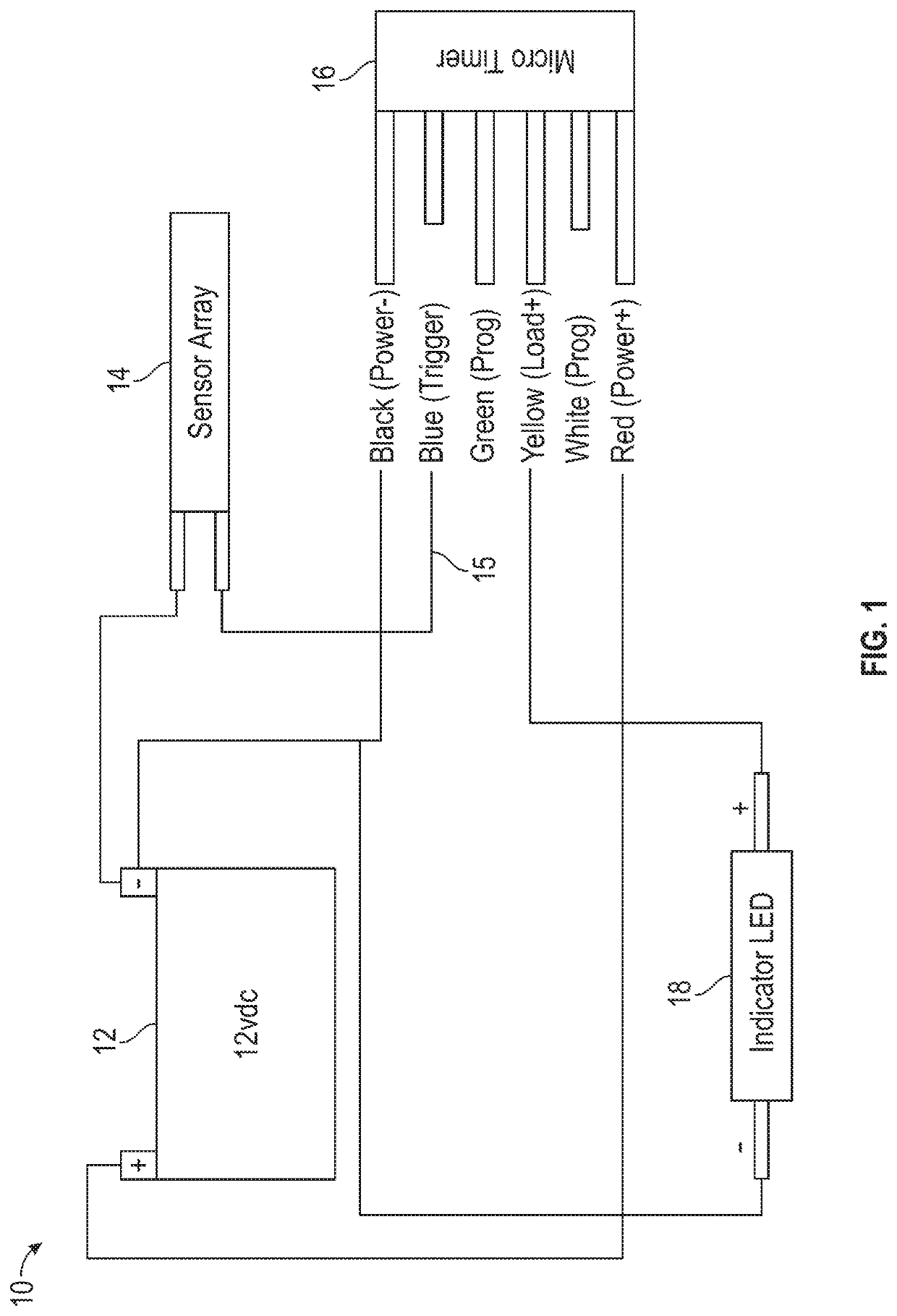
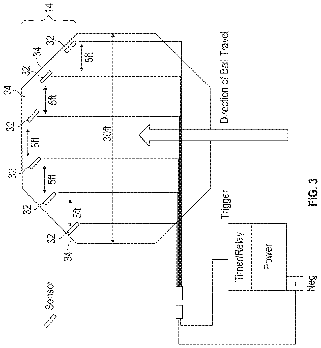
The present invention is directed to a target detection apparatus which attaches to a purpose-built or existing golf target placed on a driving range, golf course or other golfing facility for purposes of play or competition, whereby players attempt to hit their golf ball at or into the target. The invention enhances the targets functionality by enabling it to provide near instant feedback to players and others that it has been hit. Through the use of a sensor and indicator system, the target of a preferred embodiment can sense a golf ball hitting it or landing in it and draw the attention of the player or others through an indicator, which is currently a LED array. The design consists of an array of vibration sensors, each attachable to the target landing surface.

Description

FIELD OF THE INVENTION[0001]The present invention is directed towards golf targets that provide near instant feedback to players and spectators whenever the target is successfully hit. The golf targets may be purpose-designed with the invention incorporated, or upgraded by adding the invention to provide this functionality. The feedback is through an indicator, which is typically a LED array.BACKGROUND[0002]The number of U.S. golfers has dropped 24 percent since 2002, losing over a million players in 2013 alone (source: “How Golf got Stuck in The Rough,” Bloomberg BusinessWeek, Jun. 23-29 2014 at pp. 23-24). One of the reasons for the decreased popularity of golf, especially amongst the millennials, is the time it takes to play an 18-hole golf course (approximately four hours) and the lack of mass social interaction afforded players. The decreasing in popularity of the game of golf is a problem that remains largely unsolved. As a result, during the decade to 2016, approximately 800 ...

Claims


Application Information

Patent Timeline
IPC IPC(8): A63B67/02A63B63/00A63B71/06
CPCA63B63/00A63B2220/801A63B2220/833A63B2210/50A63B71/0622A63B2207/02A63B67/02A63B2102/32A63B2071/0625A63B2209/10A63B2220/62A63B2220/64A63B2225/50A63B57/40A63B2225/74
Inventor BUSH, SHANE
Owner BUSH SHANE
Learn More