Chuck device

a chuck and chuck technology, applied in the direction of chucks, mechanical devices, manufacturing tools, etc., can solve the problems of increasing the manufacture cost of the chuck device, the risk of the working fluid being scattered away before reaching the cutting edge, and the insufficient supply of working fluid to the cutting edg

Active Publication Date: 2020-02-06
DAISHOWA SEIKI CO LTD
View PDF0 Cites 0 Cited by
  • Summary
  • Abstract
  • Description
  • Claims
  • Application Information

AI Technical Summary

Benefits of technology

[0008]With the chuck device disclosed in PTL 2, since the discharging direction of the working fluid is set opposite to the rotational direction, the influence of the rotational force of the chuck device affecting the working fluid can be further lessened. With this, it is possible to reduce the amount of scattering of the discharged working fluid to the radial outer side of the cutting tool, as a result, a large amount of the working fluid can be supplied to the cutting tool. However, for effective reduction in the scattering amount of the work fluid described above, there has remained room for improvement in setting the discharging direction of the working fluid in the chuck device appropriately.
[0017]With the above-described configuration in which the chuck device includes therein a passage in which a working fluid flows and a discharge opening communicated to the passage and a discharging direction of the working fluid from the discharge opening is set opposite to a rotational direction of the cutting tool, it is possible to lessen the influence of the rotational force of the chuck device to the working fluid. Further, with the inventive configuration, the discharging direction of the working fluid from the discharge opening is set with a tilt of an angle θ to a tangential direction of a rotation trajectory of the discharge opening relative to a direction of an axis of the cutting tool and there is provided a mathematical formula for calculating an appropriate angle θ. Therefore, by using such angle θ calculated by the mathematical formula, the discharging direction of the working fluid can be set appropriately and easily also in the chuck device.
[0019]With the above-described arrangement of the discharging direction being set to be directed toward the axis of the cutting tool, the working fluid discharged from the discharge opening can be easily supplied toward the cutting tool.
[0024]With the above-described arrangement, for the circumferential speed V at the discharge opening due to the rotation of the chuck device calculated by Formula 2 and the angle θ for setting the discharging direction of the working fluid, respective numerical ranges are specified. Here, comparison between Formula 2 for calculating the circumferential speed V and Formula 1 for calculating the angle θ show that the numerators of both these formulae are same (n×Dc×n) and the circumferential speed V and the angle θ have a proportional relationship of the greater the circumferential speed V, the greater the angle θ. Thus, by associating the circumferential speed V with the angle θ, an appropriate angle θ based on the circumferential speed V can be set easily.

Problems solved by technology

Yet, with the chuck device disclosed in PTL 1, since the nozzle hole is provided at a position away from the cutting tool, there is a risk of the working fluid being scattered away before reaching the cutting tool.
In this case, however, there is a need to improve the pressure-resistant performance of the chuck device as a whole, so the manufacture cost of the chuck device will increase.
For this reason, the working fluid supplied to the cutting tool may be bounced back from the cutting tool to be scattered about, so that a sufficient amount of the working fluid may not be supplied to the cutting edge.

Method used


Image

  • Chuck device
  • Chuck device
  • Chuck device

Examples


example 1

[0052]The cutter diameter D of the cutting tool B to be gripped by the chuck device A was varied between 3 mm or less to 32 mm. The rotational speed of the chuck device A was set in correspondence with cutting speed range from 100 to 500 m / min. However, if the cutter diameter D becomes less than 3 mm, a special machine tool will be needed which can cope with high speeds in order to satisfy the cutting speed ranging from 100 to 500 m / min. Thus, in the case of the cutter diameter less than 3 mm, the rotational speed of the chuck A was set to the range of from 10,000 to 50,000 min−1 possible with a standard machine tool.

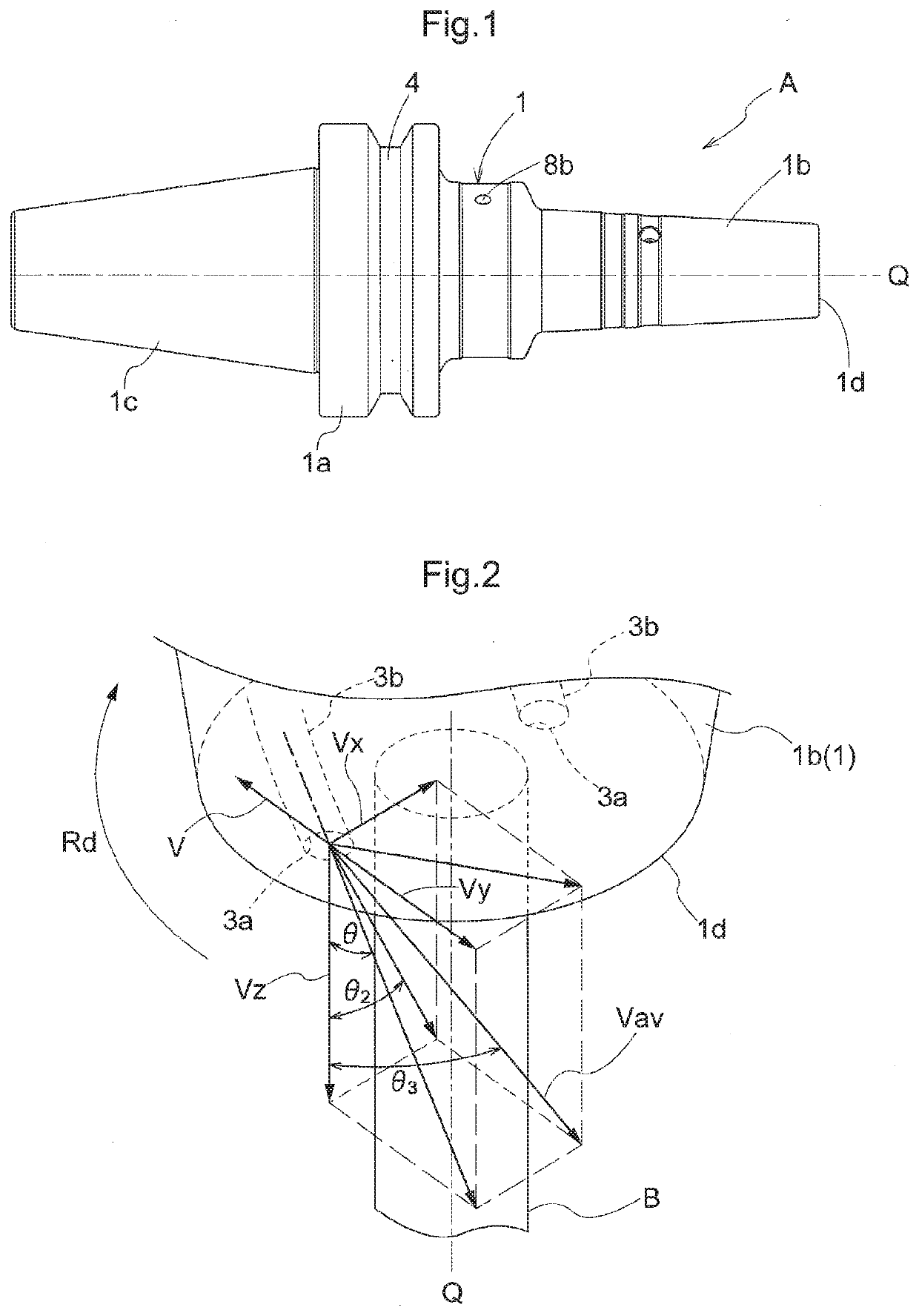
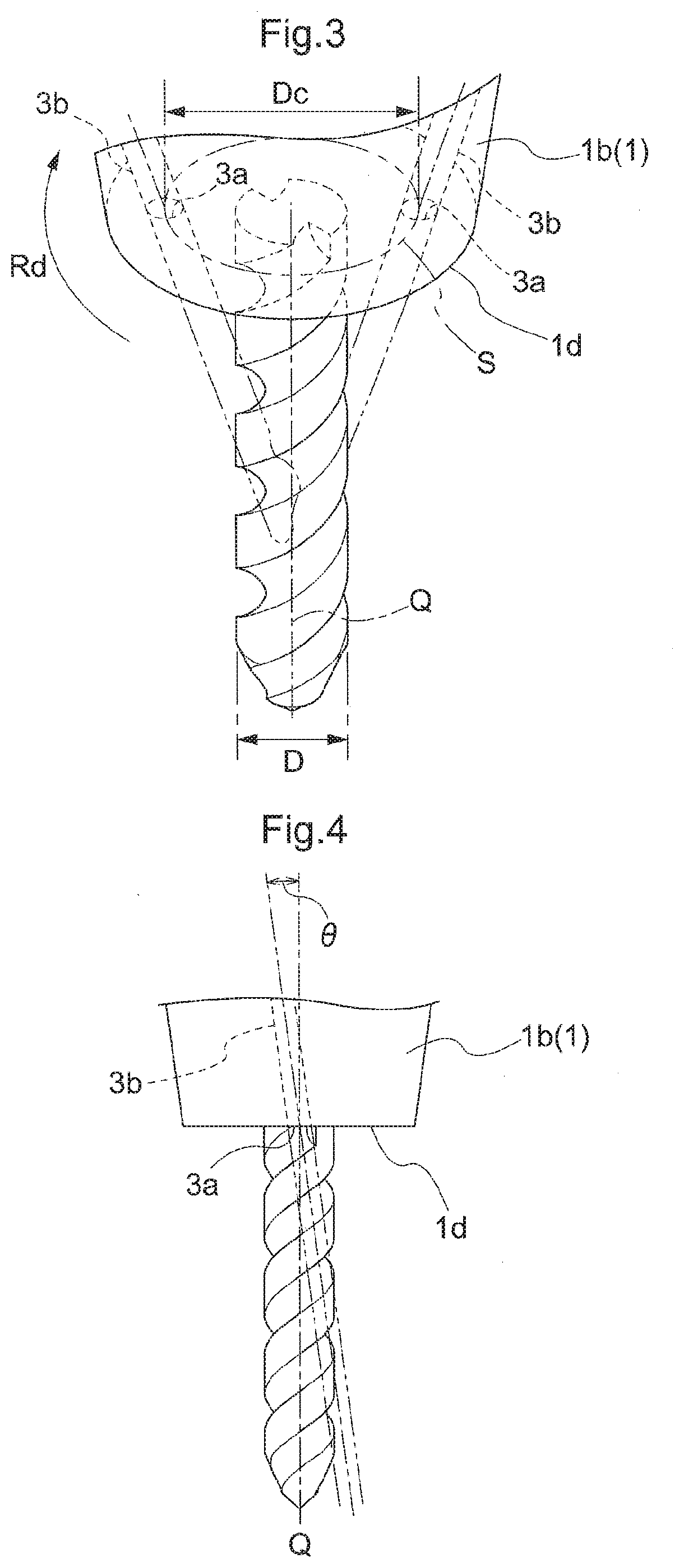
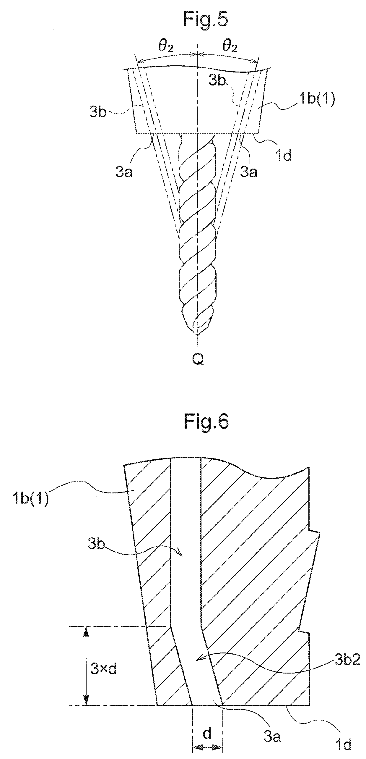
[0053]In correspondence with the cutter diameter D, the range of the diameter Dc of the virtual circle S formed by the rotation trajectory of the center of the discharge opening 3a and the range of the rotational speed n of the chuck device A were set. The coolant pressure (working fluid pressure) P at the discharge opening 3a was maintained from 3 to 7 MPa. Ranges of t...

example 2

[0054]There is disclosed an example using a special machine tool capable of rotating the chuck device A at a high speed without reducing the rotational speed of the chuck device A even when the cutter diameter D is increased. The cutter diameter D was varied from 3 mm or less to 32 mm and in correspondence with such cutter diameter D, the range of the diameter Dc of the virtual circle S formed by the rotation trajectory of the center of the discharge opening 3a was set. The rotational speed n of the chuck device A was maintained in the range from 25,000 to 35,000 min−1. The coolant pressure (working fluid pressure) P at the discharge opening 3a was maintained from 3 to 7 MPa. Ranges of the circumferential speeds V and the angle θ calculated based on these are shown in Table 2 below

TABLE 2virtualcirclediameterdischargeDc atopeningcutterdischargerotationalcircumferentialcoolantdiameter Dopeningspeed nspeed Vpressureθ[mm][mm][min−1][m / s][MPa][degrees]3 or less 6~1625,000~35,000 7.9~29....


PUM


Abstract

Provided is a chuck device that allows appropriate and easy setting of a discharging direction of working fluid. A chuck device configured to be attached to a spindle of a machine tool for gripping a cutting tool, in which inside the chuck device, there are provided a passage in which a working fluid flows and a discharge opening provided at a leading end opening of the passage through which the working fluid is discharged toward to the cutting tool. A discharging direction of the working fluid from the discharge opening is set opposite to a rotational direction of the cutting tool and set with a tilt of an angle calculated by a mathematical formula to a tangential direction of a rotation trajectory of the center of the discharge opening relative to a direction of an axis of the cutting tool.

Description

TECHNICAL FIELD[0001]This invention relates to a chuck device capable of supplying working fluid to a cutting tool.BACKGROUND ART[0002]A chuck device is attached to a spindle of a machine tool and used for holding the cutting tool. In such chuck device, a passage of the working fluid is sometimes provided for supplying a necessary amount of working fluid from this passage to the cutting tool engaged in a cutting work. The working fluid referred to herein is liquid or gas to be supplied for such purpose as cooling of a cutting edge which becomes heated due to friction with a work to be machined or flushing away cutting or milling debris. For allowing such working fluid to be supplied to a cutting tool engaged in a cutting work, chuck devices provided with variety of improvements have been developed.[0003]For instance, in the case of a chuck device disclosed in PTL 1, in order to discharge working fluid through a nozzle hole to a cutting edge, the nozzle hole is formed obliquely to be...

Claims


Application Information

Patent Timeline
Patent Type & Authority Applications(United States)
IPC IPC(8): B23Q11/10B23Q3/12B23B47/00
CPCB23B47/00B23Q11/1015B23Q3/12B23Q11/1023B23B2231/24B23Q11/10Y10T279/17111
Inventor DOI, MASAYUKI
Owner DAISHOWA SEIKI CO LTD
Why Eureka
Try Eureka