Efficient cotton gin

A cotton gin, high-efficiency technology, applied in the direction of separating plant fibers from seeds, etc., can solve the problems of low processing efficiency, high labor intensity, accumulation and compaction of seed cotton, etc., and achieve stable and efficient automatic feeding process. The effect of improving processing efficiency and increasing the contact area

Active Publication Date: 2021-04-06
徐州天虹银联纺织有限公司
View PDF8 Cites 0 Cited by
  • Summary
  • Abstract
  • Description
  • Claims
  • Application Information

AI Technical Summary

Problems solved by technology

[0003] The purpose of the present invention is to provide a high-efficiency cotton gin to solve the problem that the structure of the existing top roller cotton gin proposed in the above-mentioned background technology is limited, resulting in a small contact area between the top roller and the seed cotton, which in turn causes the existing cotton gin The machining efficiency is not high, and the automatic feeding device used in the existing cotton gin is not equipped with a breaking structure, which tends to cause the seed cotton to accumulate and compact during the conveying process, which in turn leads to the accident of conveying stuck, while manual feeding The labor intensity is high, the production cost is high, and it is not practical to use, and the separation equipment of the existing cotton gin is an open structure, and the separation of lint from the seed cotton will inevitably produce debris dust, which is scattered in the air It not only pollutes the surrounding environment, but also maintains the health of the surrounding operators, and there are certain safety hazards in use.

Method used


Image

  • Efficient cotton gin
  • Efficient cotton gin
  • Efficient cotton gin

Examples


Embodiment Construction

[0032] The following will clearly and completely describe the technical solutions in the embodiments of the present invention with reference to the accompanying drawings in the embodiments of the present invention. Obviously, the described embodiments are only some, not all, embodiments of the present invention. Based on the embodiments of the present invention, all other embodiments obtained by persons of ordinary skill in the art without making creative efforts belong to the protection scope of the present invention.

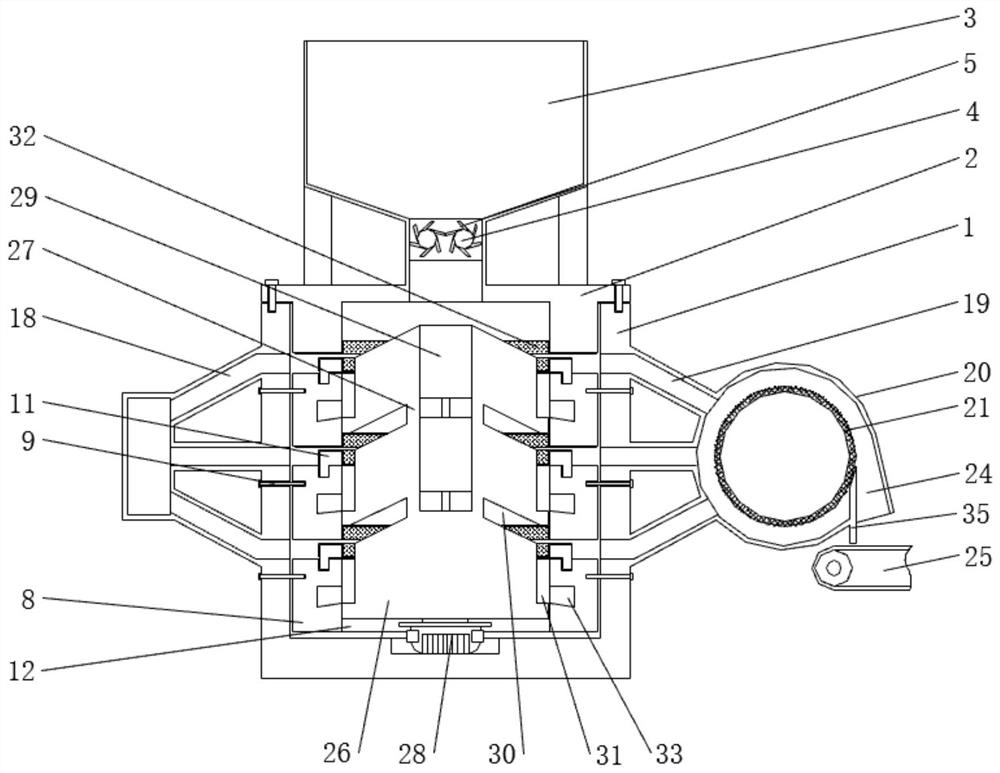
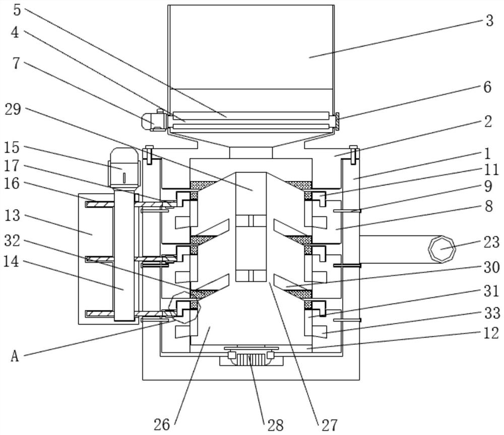
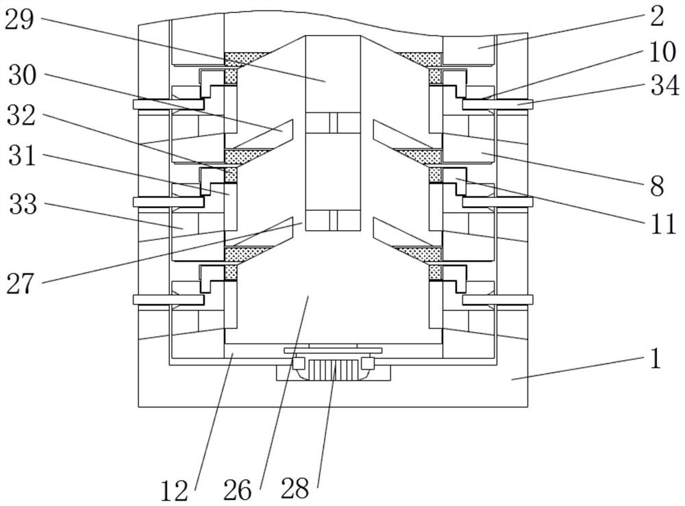
[0033] see Figure 1-9 , the present invention provides a technical solution: a high-efficiency cotton gin, such as figure 1 , figure 2 , image 3 and Figure 6 As shown, a box cover 2 is fixedly installed on the top of the box body 1, and a silo 3 is fixed above the box cover 2. The lower end of the hopper 3 runs through the box cover 2 and communicates with the box body 1. Rotating shaft 4, and claws 5 are fixed on the outer sides of the two rotating sh...


PUM


Abstract

The invention discloses an efficient cotton gin. The efficient cotton gin comprises a box body, a fixed table, a connecting frame, an air inlet channel, a guide plate, a seed discharging channel and a limiting pin, wherein a box cover is fixedly installed at the top of the box body; a material bin is fixed to the upper portion of the box cover; the lower end of the material bin penetrates through the box cover and communicates with the box body; two rotating shafts are rotatably connected to the lower side in the material bin; shifting pawls are fixed to the outer sides of the two rotating shafts; the front ends of the two rotating shafts penetrate through the material bin and are connected through a gear set; and the rear end of one rotating shaft penetrates through the material bin and is connected with a first motor fixedly installed on the rear side of the material bin. The efficient cotton gin is provided with the fixed table, the box cover and a rotating table; when the rotating table is driven to rotate, a rubber layer on the upper side of the rotating table is matched with a rubber layer on the lower side of the corresponding fixed table or the lower side of the corresponding box cover to peel ginned cotton in unginned cotton; the contact area of the unginned cotton is increased through multiple layers of peeling structures sequentially arranged in an up-down manner; and under the condition that cotton fibers are not damaged, the processing efficiency of the cotton gin is greatly improved.

Description

technical field [0001] The invention relates to the technical field of cotton gins, in particular to a high-efficiency cotton gin. Background technique [0002] Cotton gin is a kind of cotton processing equipment, which is used to separate lint from seed cotton. Commonly used cotton gins include sawtooth gins and roller gins, and because sawtooth gins are easy to damage cotton fibers during processing , so the top roller gin is usually used when processing high-grade cotton, but the existing top roller gin is limited by the structure, resulting in a small contact area between the top roller and the seed cotton, which in turn leads to the low processing efficiency of the existing cotton gin , and the automatic feeding device used in the existing cotton gin is not equipped with a breaking structure, which is easy to accumulate and compact the seed cotton during the conveying process, which in turn leads to the accident of conveying stuck, and the manual feeding is labor-intens...

Claims


Application Information

Patent Timeline
IPC IPC(8): D01B1/04
CPCD01B1/04
Inventor 许冬梅陈明超王传响于勇
Owner 徐州天虹银联纺织有限公司
Why Eureka
Try Eureka