Cell transfer apparatus

Inactive Publication Date: 2020-02-06
YAMAHA MOTOR CO LTD
View PDF0 Cites 0 Cited by
  • Summary
  • Abstract
  • Description
  • Claims
  • Application Information

AI Technical Summary

Benefits of technology

[0006]The present disclosure provides a cell transfer apparatus, which transfers cells to a microplate having wells for receiving the cells from a dish i

Problems solved by technology

Use of such a tip for sucking the second cell might cause intrusion of the first cell to the

Method used


Image

  • Cell transfer apparatus
  • Cell transfer apparatus
  • Cell transfer apparatus

Examples


Example

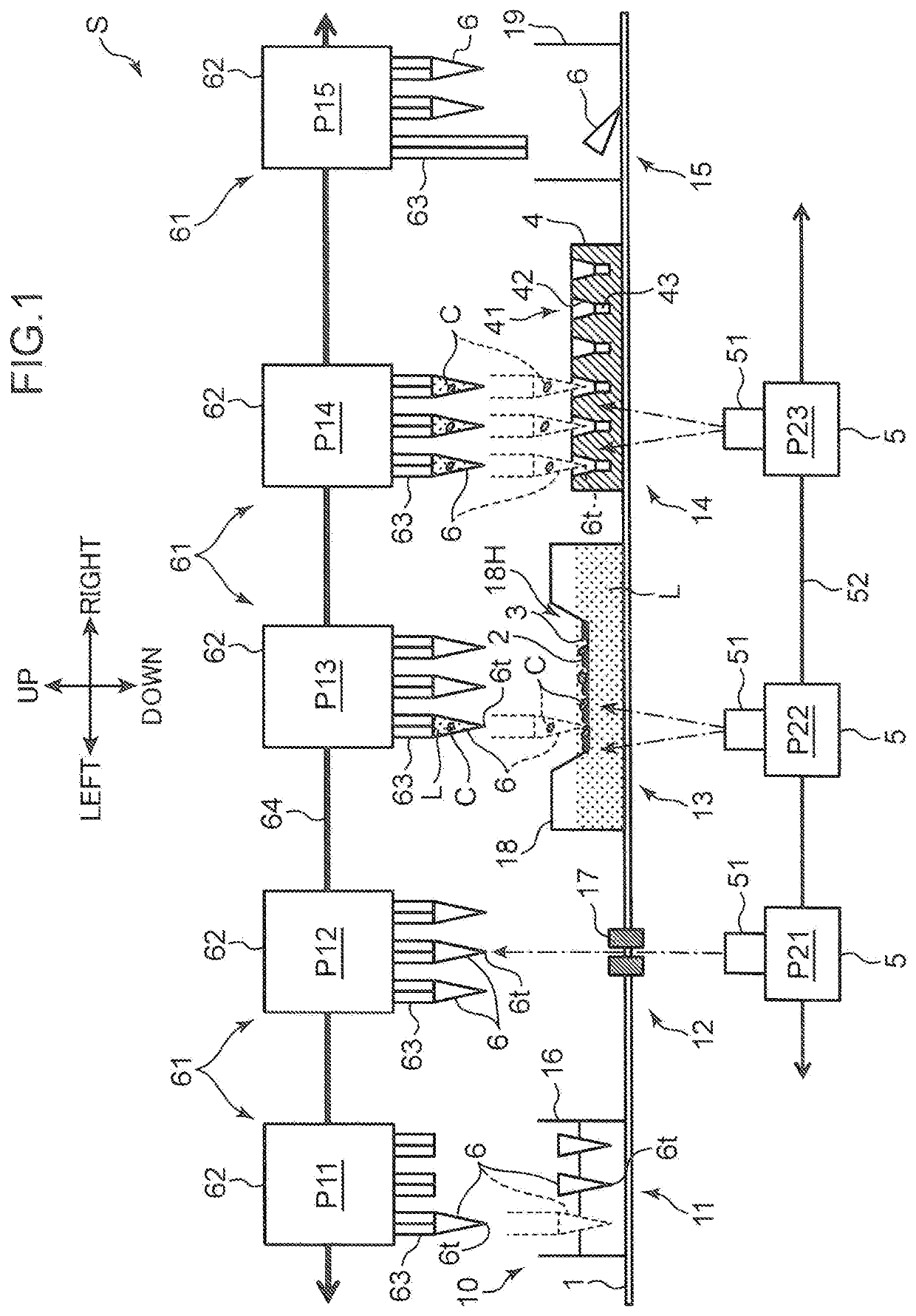
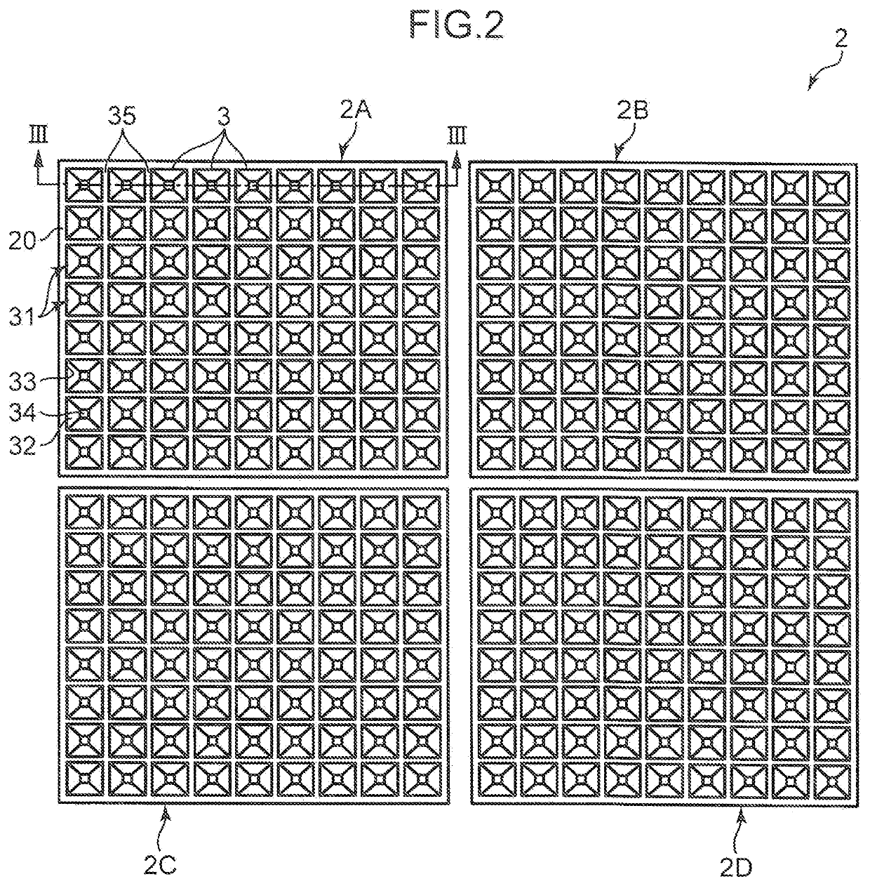
[0069]A cell sucking and discharging mode according to a first embodiment in the case where a plurality of specimens are present will be described below with reference to FIG. 8. The head unit 61 including the eight tips 6A to 6H is used, and the microplate 4 including the wells 41 of 24 rows×16 columns is used. That is, the conditions are equal between the first embodiment and the comparative example. Four specimens 1 to 4 are present, and cells C of the specimens 1 to 4 are supported by the first to fourth dishes 2A to 2D, respectively (FIG. 2).

[0070]In the present embodiment, the eight heads 63A to 63H (the tips 6A to 6H) are allocated to the specimens 1 to 4. FIG. 8 illustrates an example where the tips 6A and 6B are allocated to (specified for) the specimen 1 (the first specimen head), the tips 6C and 6D are allocated to the specimen 2 (the second specimen head), the tips 6E and 6F are allocated to the specimen 3, and the tips 6G and 6H are allocated to the specimen 4.

[0071]In ...


PUM


Abstract

A cell transfer apparatus includes a controller that controls generation of a suction force and a discharge force at a plurality of heads and controls movement of a head unit. The controller executes a process for specifying first and second specimen heads to be used for transferring the first and second specimens, a process for specifying first and second specimen wells to be used for receiving the first and second specimens, a process for sequentially sucking the cell of the first specimen from the first dish by the first tip attached to the first specimen head and then the cell of the second specimen from the second dish by the second tip, and a process for discharging the cell of the first specimen from the first tip to the first specimen well and the cell of the second specimen from the second tip to the second specimen well.

Description

CROSS-REFERENCE TO RELATED APPLICATION[0001]This application is a National Stage of International Patent Application No. PCT / JP2017 / 032059, filed Sep. 6, 2017, which claims benefit of priority to Japanese Patent Application No. 2016-204575, filed Oct. 18, 2016, the entire content of each are incorporated herein by reference.BACKGROUNDTechnical Field[0002]The present disclosure relates to a cell transfer apparatus that transfers cells from a dish in which the cells are held to a plate having a well for receiving the cells.Background Art[0003]For example, in a use for medical and biological studies, a single cell or a cell aggregate obtained by three-dimensionally clumping cells (hereinafter, they are simply referred to herein as cells) are accommodated in wells arranged in a matrix pattern on a microplate in some cases to be subject to processing such as observation, checking for medicinal effect, inspection, or culture. The cells to be accommodated in the wells are sorted on the dis...

Claims


Application Information

Patent Timeline
IPC IPC(8): C12M1/26C12M1/32
CPCC12M33/04C12M23/12C12M33/06
Inventor ITO, SABURO
Owner YAMAHA MOTOR CO LTD
Why Eureka
Try Eureka