

Menstrual cup capable of being easily removed
- Summary
- Abstract
- Description
- Claims
- Application Information
AI Technical Summary
Benefits of technology
Problems solved by technology
Method used
Image

Examples
first embodiment
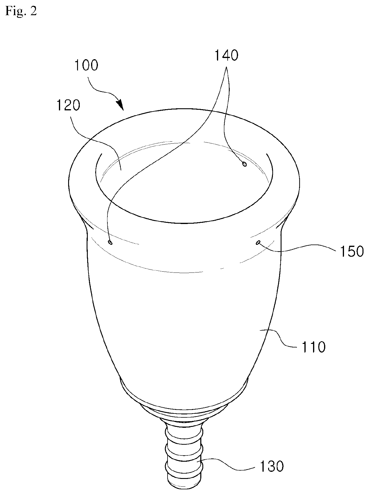
[0041]Referring to FIG. 2 first, a menstrual cup 100 according to the present invention may include a main body 110 and a handle 130.
[0042]The main body 110 of the menstrual cup 100 according to the first embodiment of the present invention is formed in a cup shape, and a storage 120 is formed in the main body 110 to store menstrual blood. In the present embodiment, a shape in which a diameter of the main body 110 increases from a lower end connected to the handle 130 toward an upper end at which an opening is formed is illustrated. However, the present invention is not limited thereto, and the main body may be formed in various shapes in which a storage is formed.
[0043]A storage 120 may be formed inside the main body 110 of the menstrual cup 100 according to the first embodiment of the present invention to serve to store menstrual blood which is discharged outside the body during menstruation. A size of the storage 120 may be formed to be varied according to a capacity to store the...
fifth embodiment
[0093]FIG. 12 is a diagram illustrating a menstrual cup according to a modified example of the present invention. Referring to FIG. 12, in the present modified example, an air flow path 511′ formed on the outer wall of the main body 510 of a menstrual cup 500′ may be formed of a plurality of spiral grooves. Even according to the above structure of the air flow path 511′, in a state in which the menstrual cup 500′ is inserted, when the handle 530 or the lower end of the main body 510 is pressed or the menstrual cup 500′ is rotated by gripping the handle 530 or the lower end of the main body 510, air may smoothly flow to the upper end of the main body 510 along the air flow path 511′.
[0094]As described above, in the fifth embodiment of the present invention and the modified example of the fifth embodiment thereof, the air may flow to the upper end of the main body 510 through the air flow path 511 or 511′ formed on the outer wall of the main body 510. Consequently, the air is introduc...
PUM
 Abstract
Description
Claims
Application Information