
Artificial lens molding mold

A technology for forming molds and intraocular lenses, which is applied in the directions of intraocular lens, prosthesis, medical science, etc., can solve problems such as affecting the molding effect and mold forming impact, and achieve the effects of eliminating internal pressure, reliable positioning, and simple mold clamping operation.

Active Publication Date: 2020-04-21
DONGGUAN HEC MEDICAL INTELLIGENT DEVICE R&D CO LTD
View PDF2 Cites 0 Cited by
  • Summary
  • Abstract
  • Description
  • Claims
  • Application Information

AI Technical Summary

Problems solved by technology

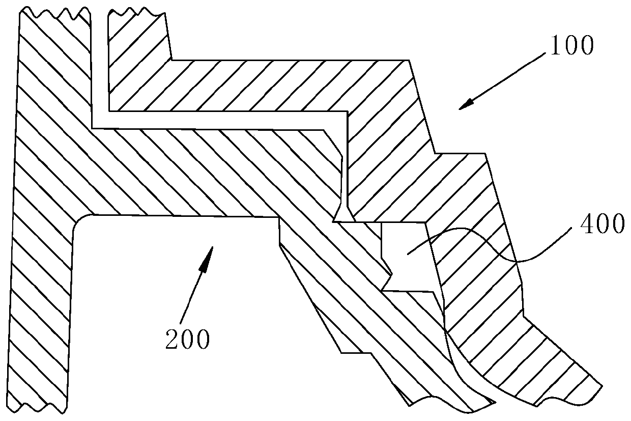
However, in the prior art, the storage cavity used as the liquid drainage area 400 is a closed cavity, and internal pressure will still be generated during the polymerization and molding process of the reaction liquid, which will cause impact on the molding of the mold and affect the molding effect

Method used


Image

  • Artificial lens molding mold
  • Artificial lens molding mold
  • Artificial lens molding mold

Examples


Embodiment 1

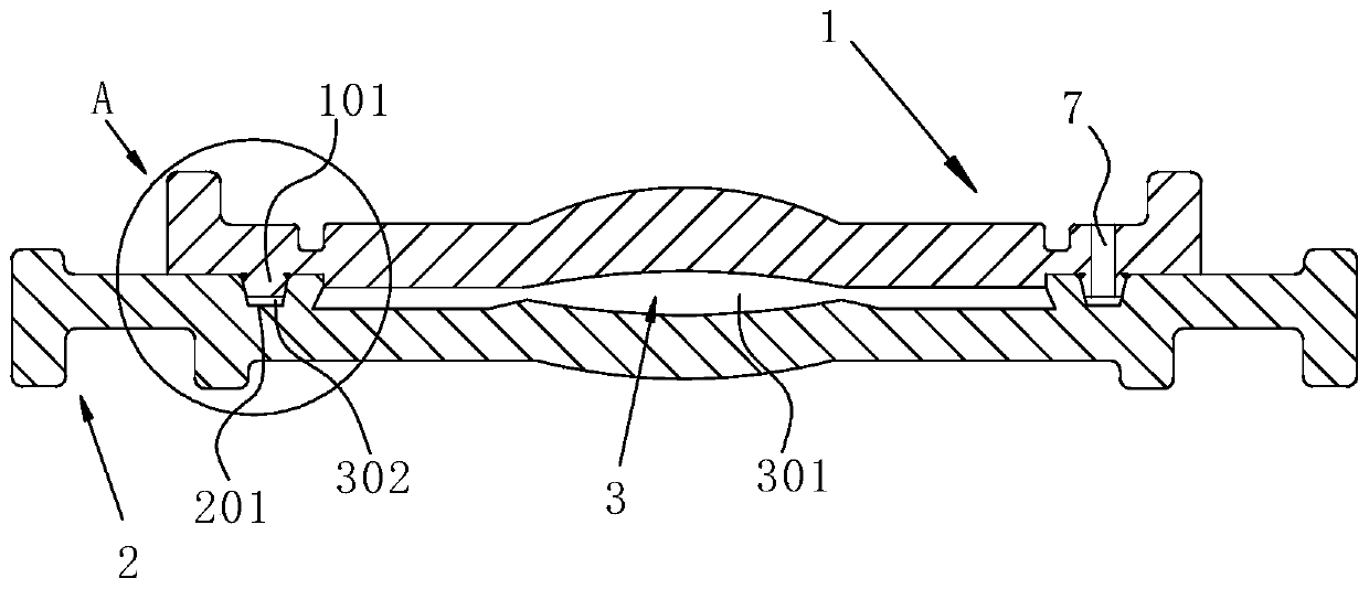
[0085] Such as image 3 As shown, a mold for forming an intraocular lens includes a male mold 1 and a female mold 2, the male mold 1 is arranged above the female mold 2, and the middle area of ​​the male mold 1 is an upwardly convex arc-shaped area, and the arc-shaped area of ​​the The centerline is the centerline of the first optical zone of the male mold 1; The bottom of the male mold 1 is rotated and extended around the circumferential direction with a positioning boss 101, and the positioning boss 101 is located outside the first optical zone, as Figure 5 As shown, the positioning boss 101 is an annular boss, the cross-sectional shape of the positioning boss 101 is trapezoidal, and the rotation axis of the positioning boss 101 is on the same straight line as the centerline of the first optical zone. The top of the female mold 2 is rotated and extended around the circumferential direction to be provided with a positioning groove 201, and the positioning groove 201 is loca...

Embodiment 2

[0094] The difference between this embodiment and Embodiment 1 is:

[0095] The cross-sectional shape of the conduction opening is circular. In other embodiments, the cross-sectional shape of the conduction opening may also be a parallelogram.

Embodiment 3

[0097] The difference between this embodiment and Embodiment 1 is:

[0098] In this embodiment, if Figure 8 As shown, the cross-sectional shape of the positioning boss 101 and the positioning groove 201 is a rectangle, wherein the protruding end of the positioning boss 101 is provided with a boss chamfer 6, the cross-sectional shape of the positioning boss 101 is designed as a rectangle, and in the positioning The protruding end of the boss 101 is provided with a boss chamfer 6, which can ensure that the positioning boss 101 can be easily inserted into the positioning groove 201, and at the same time can reduce the difficulty of making the mold and simplify the manufacturing process, thereby reducing the manufacturing cost.

[0099] Of course, in other embodiments, the cross-sectional shape of the positioning boss and the positioning groove can also be triangular. Setting a triangular shape can not only facilitate quick positioning, but also save material. The cross-sectiona...


PUM


Abstract

The invention discloses an artificial lens forming mold, comprising a male mold and a female mold; the middle of the male mold is provided with a first optical area; the male mold is provided with a positioning terrace rotationally extended along the periphery; the middle of the female mold is provided with a second optical area; the female mold is provided with a positioning groove rotationally extended along the periphery; the height of the positioning terrace is less than the depth of the positioning groove; in closing state, the positioning terrace is inserted into the positioning groove;a clearance between the positioning terrace and the positioning groove forms a liquid residue groove; the rotational axis of the positioning terrace and that of the positioning groove are collinear; the positioning terrace is provided with at least one thru port, one end of the thru port is communicated with the liquid residue groove, and the other end of the thru port is communicated with external air. Surplus reaction liquid in a forming cavity is discharged via the liquid residue groove; the thru port arranged in the positioning terrace enables the liquid residue groove to be communicated with external air, and inner pressure generated by swelling of the reaction liquid is effectively eliminated.

Description

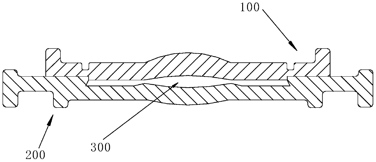
technical field [0001] The invention relates to the technical field of moulds, in particular to an artificial crystal molding mould. Background technique [0002] Such as figure 1 As shown, the IOL forming mold in the prior art is divided into upper and lower parts, the upper part is named male mold 100 , and the lower part is named female mold 200 . The combination of the male mold 100 and the female mold 200 will form a cavity 300 in which the intraocular lens is molded. [0003] In the production of crystal semi-finished products, it is necessary to add a reaction liquid to the female mold 200, and the amount of the added reaction liquid must be more than the actual demand for mold forming. In addition, mold molding needs to go through a polymerization molding process, and the reaction liquid will expand during the polymerization molding process (the test shows that the expansion rate is about 5%). The expansion will inevitably cause the liquid in the cavity 300 to form...

Claims


Application Information

Patent Timeline
Patent Type & Authority Patents(China)
IPC IPC(8): B29C33/00B29C33/30A61F2/16
CPCA61F2/16A61F2240/004B29C33/00B29C33/0055B29C33/303
Inventor 罗敏曹立
Owner DONGGUAN HEC MEDICAL INTELLIGENT DEVICE R&D CO LTD
Learn More