
Underwater non-contact power supply device

A non-contact power supply and capacitor technology, which is applied in circuit devices, underwater ships, circuits, etc., can solve the problems of increasing the pressure resistance of the coupler container, increasing the weight and size, etc.

Inactive Publication Date: 2021-07-20
SHOWA AIRCRAFT INDUSTRY
View PDF2 Cites 0 Cited by
  • Summary
  • Abstract
  • Description
  • Claims
  • Application Information

AI Technical Summary

Problems solved by technology

In other words, for example, in the design of the coupler vessel, the high strength and strong structure used to increase the pressure resistance and strength of the coupler vessel results in an increase in weight and size, which is undesirable for working and operating in deep sea

Method used


Image

  • Underwater non-contact power supply device
  • Underwater non-contact power supply device
  • Underwater non-contact power supply device

Examples


Embodiment Construction

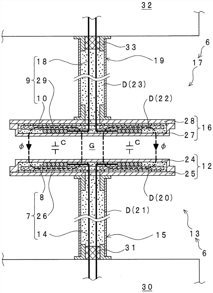
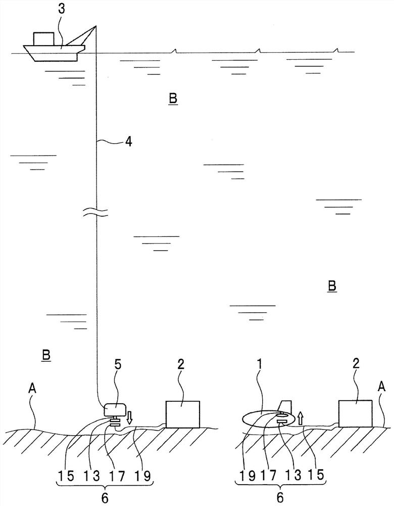
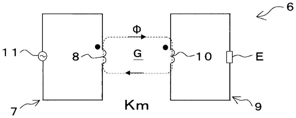
[0050] will refer to Figure 1 to Figure 3D The outline and examples of the underwater non-contact power supply device of the present invention will be described. exist Figure 1 to Figure 3D In , reference numeral 6 denotes an exemplary underwater non-contact power supply device. Like conventional devices, the underwater non-contact power supply device 6 supplies power from the power transmitting coil 8 of the power transmitting circuit 7 to the power receiving coil 10 of the power receiving circuit 9 based on the mutual inductance of electromagnetic induction. The power transmitting coil 8 and the power receiving coil 10 are positioned close to each other. The power transmitting coil 8 and the power receiving coil 10 face each other with a gap G therebetween.

[0051] refer to figure 2 , the mother ship 3 and the ROV 5 are provided with a power transmission circuit 7 . The subsea power base 2 is provided with a power receiving circuit 9 and a power transmitting circuit ...


PUM


Abstract

The invention relates to an underwater non-contact power supply device. A power transmission coupler void space (20) and a power transmission hose void space (21) are allowed to communicate with each other. A viscous resin (D) is sealed in each of the power transmission coupler void space (20) and the power transmission hose void space (21). A power reception coupler void space (22) and a power reception hose void space (23) are allowed to communicate with each other. A viscous resin (D) is sealed in each of the power reception coupler void space (22) and the power reception hose void space (23).

Description

technical field [0001] The present invention generally relates to an underwater non-contact power supply device, and more particularly, to a non-contact power supply device used in water such as the ocean. Background technique [0002] For electric vehicles and smartphones, for example, so-called non-contact power supply that supplies power without mechanical contact with cables or the like has been continuously developed. For example, wireless power is already in practical use in smartphones. The wireless power delivery device is called a wireless power transmission (WPT) device. The non-contact power supply device on land supplies power based on the mutual inductance of electromagnetic induction. Specifically, for example, a power receiving coil of a power receiving circuit mounted on a vehicle or the like is positioned relative to a power transmitting coil of a power transmitting circuit fixed on a road surface or the like, and electric power is supplied from the power ...

Claims


Application Information

Patent Timeline
Patent Type & Authority Applications(China)
IPC IPC(8): H02J50/10H01F38/14
CPCH01F38/14H02J50/10Y02T10/70Y02T10/7072Y02T90/14B60L53/12Y02T90/12B60L2200/32B63G8/001B60L53/122H02J50/12H02J50/005
Inventor 山本喜多男渡边浩史望月正志冲米田恭之渡边敦
Owner SHOWA AIRCRAFT INDUSTRY
Learn More