Vehicle lamp and lighting control method thereof

a technology for vehicle lamps and control methods, applied in semiconductor devices for light sources, light and heating apparatus, transportation and packaging, etc., can solve problems such as inability to solve stabilize, and incongruity and discomfort of drivers

Active Publication Date: 2020-02-13
KOITO MFG CO LTD
View PDF0 Cites 4 Cited by
  • Summary
  • Abstract
  • Description
  • Claims
  • Application Information

AI Technical Summary

Benefits of technology

[0006]With respect to such a problem, in the prior application (JP-A-2017-199342) previously filed by the present applicant, there has been proposed a technique of continuing the rotation of the rotating mirror until a predetermined time elapses when a first lamp unit (light scanning lamp) is turned off. Accordingly, when the first lamp unit is turned off, the rotating mirror is maintained at a predetermined rotational speed as long as the first lamp unit is turned on again within the predetermined time, and thus it is possible to prevent the senses of incongruity and discomfort as described above.
[0008]An object of the present invention is to provide a vehicle lamp and a lighting control method thereof in which senses of incongruity and discomfort when a light scanning lamp is turned on are prevented.

Problems solved by technology

Therefore, during an initial rise time during which the light scanning lamp is turned on, flickering of the illumination occurs with a change in the rotational speed of the motor, causing a driver to feel incongruity and discomfort.
Therefore, when turning-on is performed in which the rotating mirror is rotated based on the illumination instruction of the first lamp unit, there are cases where the senses of incongruity and discomfort which occur before the rotational speed of the rotating motor stabilizes cannot be always solved, and further improvement is required.

Method used


Image

  • Vehicle lamp and lighting control method thereof
  • Vehicle lamp and lighting control method thereof
  • Vehicle lamp and lighting control method thereof

Examples


Embodiment Construction

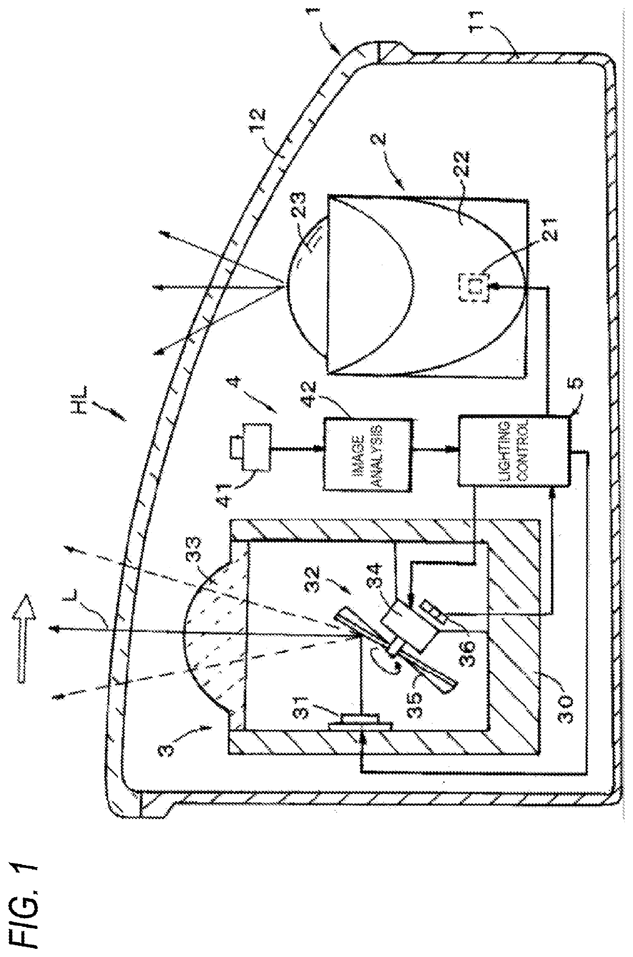
[0031]Next, an embodiment of the present invention will be described with reference to the drawings. FIG. 1 is a schematic horizontal sectional view of a head lamp HL of an automobile to which the present invention is applied. The head lamp HL includes a lamp housing 1 configured by a lamp body 11 and a translucent front cover 12, and a low beam lamp unit 2 and a high beam lamp unit 3 mounted in the lamp housing 1. In the following description, a front-rear direction is a direction based on front-rear directions of the automobile and a lamp.

[0032]The low beam lamp unit 2 is a first lamp in the present invention, is configured as a projector type lamp unit, and includes a first white LED (light emitting diode) 21 used as a light source configured to emit white light, a reflector 22 configured to reflect the white light emitted from the first white LED 21 in a light collecting state, and a projection lens 23 configured to project the white light collected by the reflector 22 to a fron...


PUM

PropertyMeasurementUnit
areaaaaaaaaaaa
timeaaaaaaaaaa
reflection angleaaaaaaaaaa

Abstract

A vehicle lamp and a lighting control method thereof which prevent senses of incongruity and discomfort when a light scanning type lamp is turned on. The vehicle lamp includes a first lamp (a low beam lamp unit) 2 configured to illuminate a required area when turned on, a second lamp (a high beam lamp unit) 3 configured to illuminate an area different from the required area when turned on, and a lighting control device 5 configured to control lighting of the first lamp and the second lamp. The second lamp is configured as a light scanning type lamp including a light source 31 and a scanning means 32 (a motor 34, a rotating mirror 35) configured to scan light emitted from the light source. The lighting control device drives the scanning means of the second lamp when the first lamp is turned on.

Description

CROSS-REFERENCE TO RELATED APPLICATIONS[0001]This application is based on and claims priority under 35 USC 119 from Japanese Patent Application No. 2018-151020 filed on Aug. 10, 2018.TECHNICAL FIELD[0002]The present invention relates to a vehicle lamp which performs a light scanning type illumination and a lighting control method thereof.BACKGROUND ART[0003]In order to enhance a safety traveling performance of a vehicle such as an automobile, there has been proposed a technique for detecting an object such as a preceding vehicle, an oncoming vehicle, or a pedestrian in front of the automobile and controlling light distribution so as not to dazzle a detected object. For example, an adaptive driving beam (ADB) light distribution control of an automobile is a light distribution control which does not selectively illuminate an object existing in an area other than an illumination area of a low beam light distribution, in particular, an area above a cut-off line of the low beam light dis...

Claims


Application Information

Patent Timeline
Patent Type & Authority Applications(United States)
IPC IPC(8): B60Q1/08F21S41/675F21S41/32
CPCF21S41/675B60Q1/085F21Y2115/10B60Q2300/45F21S41/32B60Q2300/42F21V23/04B60Q1/14B60Q1/076F21W2102/135F21W2107/10B60Q1/143B60Q2300/052B60Q2300/056
Inventor TAKII, NAOKIMURAYAMA, MASATSUGU
Owner KOITO MFG CO LTD
Why Eureka
Try Eureka