Offset Weight-Powered Engine

Inactive Publication Date: 2020-02-13
TRANER C MIKE
View PDF38 Cites 2 Cited by
  • Summary
  • Abstract
  • Description
  • Claims
  • Application Information

AI Technical Summary

Benefits of technology

[0007]The rotating body may also include exterior weights, such as along the perimeter of the rotating body near the terminal points of the radial arms. This may be done to increase the overall rotational inertia of the rotating body to damp vibrations or output fluctuations.
[0008]The lever arms function by creating an offset weighting effect on the rotating body. Lever arms possess a moment arm acting on the central axle, controlled by their own weight, and the weight supported thereby (such as exterior weights and the rotating weight arms), the weight distribution thereof, and their orientation to gravity.
[

Problems solved by technology

The problem of power

Method used


Image

  • Offset Weight-Powered Engine
  • Offset Weight-Powered Engine
  • Offset Weight-Powered Engine

Examples


first embodiment

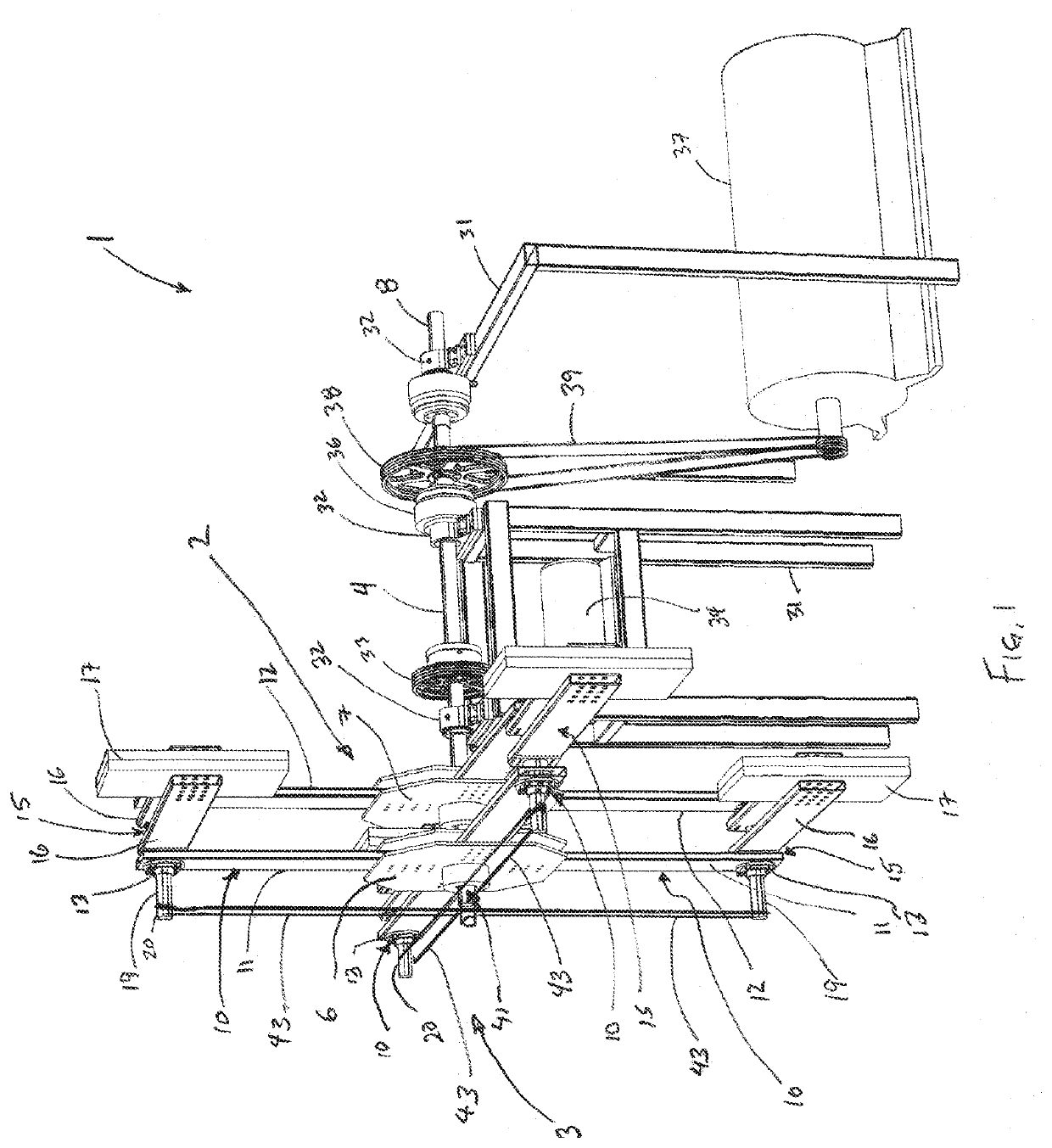
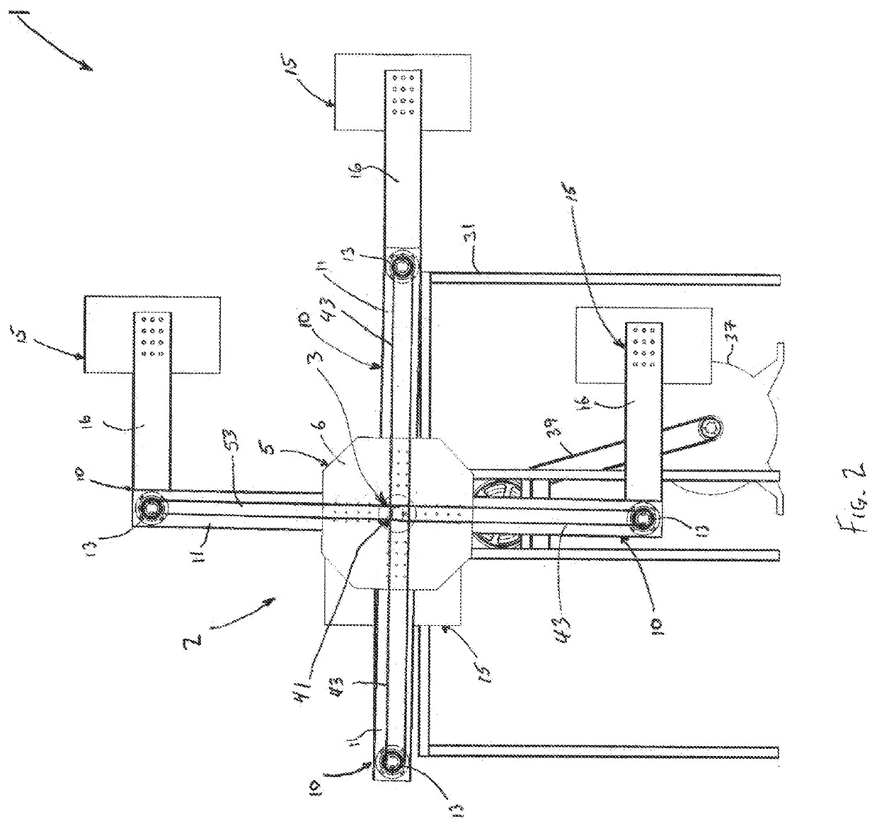
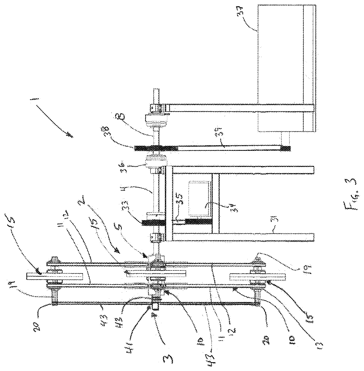
[0028]the power generating system is shown in FIGS. 1-3. System 1 includes main assembly 2 and control gearing assembly 3.

[0029]Main assembly 2 includes main shaft 4, hub assembly 5 mounted on main shaft 4, four main arm assemblies 10 mounted on hub assembly 5 at right angles to each other and at right angles to main shaft 4, and four power arm assemblies 15 mounted on main arm assemblies 10. Hub assembly 5, in this embodiment is formed of front & rear bracket sets 6&7, each rotationally fixed to main shaft 4 and extending perpendicular to its axis of rotation. Main arm assemblies 10 include front & rear arms 11&12. Front & rear arms 11&12 are parallel to one another, extending radially outward from main shaft 4, and are mounted at their proximal ends on, respectively front & rear bracket sets 6&7. At or near the distal (radially-outward) ends of front & rear arms 11&12 are bearing sets 13. Bearing sets 13 are fixed axially parallel to each other, and each support a power arm assemb...

second embodiment

[0035]the power generating system is shown in FIGS. 4-6. System 101 includes main assembly 2 and control assembly 151. Structures common to the FIGS. 1-3 retain the same numbering, and some have been omitted from FIGS. 4-6 in the interests of clarity.

[0036]Main assembly 2 includes main shaft 4, hub assembly 5 mounted on main shaft 4, four main arm assemblies 10 mounted on hub assembly 5 at right angles to each other and at right angles to main shaft 4, and four power arm assemblies 15 mounted on main arm assemblies 10. Hub assembly 5, in this embodiment is formed of front & rear bracket sets 6&7, each rotationally fixed to main shaft 4 and extending perpendicular to its axis of rotation. Main arm assemblies 10 include front & rear arms 11&12. Front & rear arms 11&12 are parallel to one another, extending radially outward from main shaft 4, and are mounted at their proximal ends on, respectively front & rear bracket sets 6&7. At or near the distal (radially-outward) ends of front & r...


PUM


Abstract

An offset weight-powered engine uses gravity to create an unbalanced net moment arm on the engine to overcome the moment of inertia and to produce rotational motion which is converted to energy out of the system. Weights on rotatable arms extend from peripheral points on the main body of the engine, which rotates on a main shaft. The weights are held off-vertical during in a stable, but unbalanced, configuration, to provide leverage and create an over-leveraged situation. This creates a rotational force generating torque and allowing the system to generate power. The rotating weights are maintained in an off-vertical position by a control system. A rotating control assembly holds those weighted arms in position, rotating in unison with the weight arms with a main shaft parallel but offset from the main shaft of the main body, and rotatable arms fixed to the weighted arms and compensating for the offset.

Description

TECHNICAL FIELD[0001]The present invention relates engines deriving power from torque generated by offset weighting and powered by gravity.BACKGROUND OF THE INVENTION[0002]The problem of power generation is age-old. Previously, power was created using fossil fuel-powered engines, and more currently, technology has led to solar and wind powered power generation. It is desirable to eliminate the need for fossil fuels or radioactive elements to generate electricity without harmful emissions or a large carbon footprint. It is also desirable to produce reliable power 24 hours a day, 7 days a week.[0003]An offset weight-powered engine, that is continuously rotating, gravity-powered, generating torque, is similar to a water wheel or windmill, and uses the natural force of gravity as the means to create an unbalanced net moment arm on the engine to overcome the moment of inertia on the apparatus to produce rotational motion which is converted to energy out of the system. Rotating weights ar...

Claims


Application Information

Patent Timeline
IPC IPC(8): F03G3/00F03G7/10
CPCF03G7/10F03G3/00F03G7/107
Inventor TRANER, CHARLES MICHAELWARTHAN, JERRY GENE
Owner TRANER C MIKE
Why Eureka
Try Eureka