Light guide plate, planar light source apparatus, display apparatus, and electronic device
a light guide and display device technology, applied in the direction of lighting and heating devices, planar/plate-like light guides, instruments, etc., can solve the problem of non-uniformity of brightness in liquid crystal display devices, and achieve the effect of suppressing the non-uniformity of brightness in an area and suppressing the decline of contrast between areas
- Summary
- Abstract
- Description
- Claims
- Application Information
AI Technical Summary
Benefits of technology
Problems solved by technology
Method used
Image
Examples
first specific example
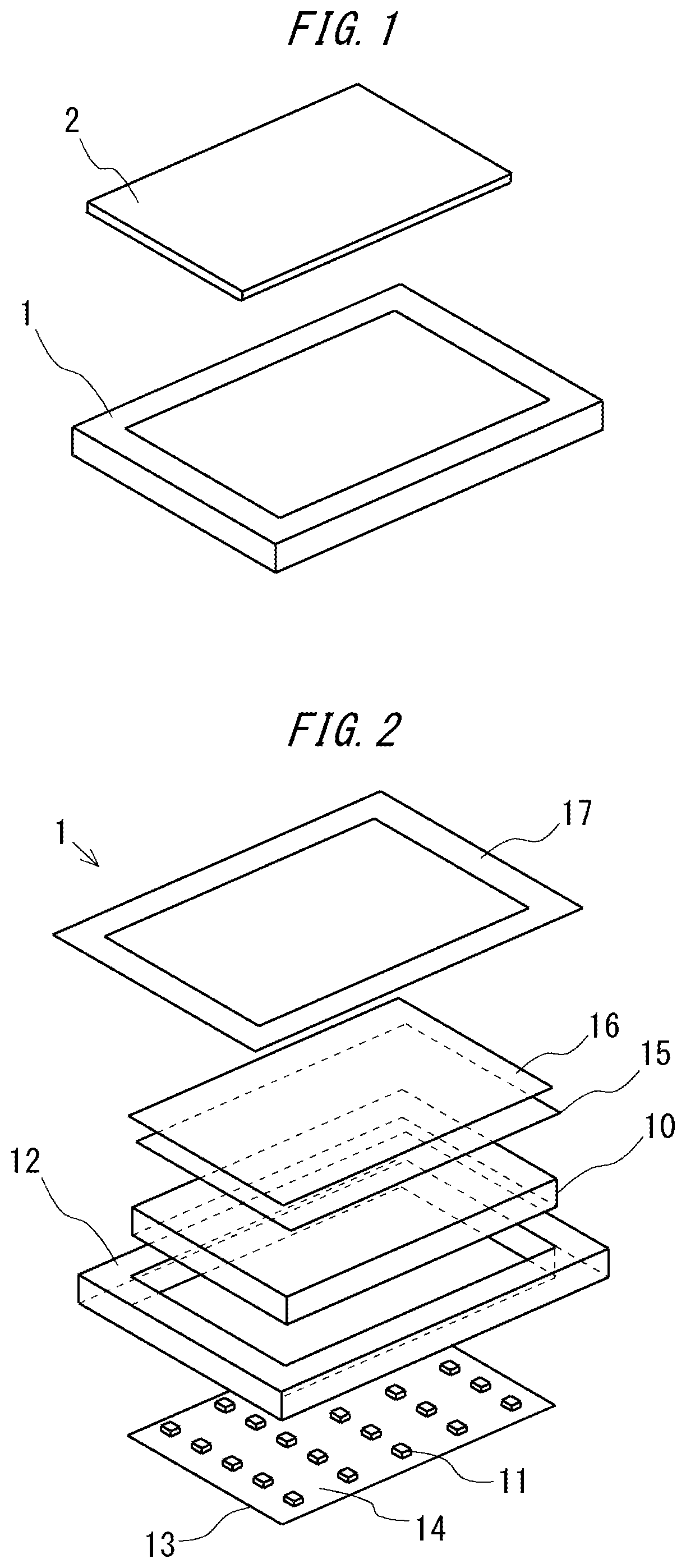
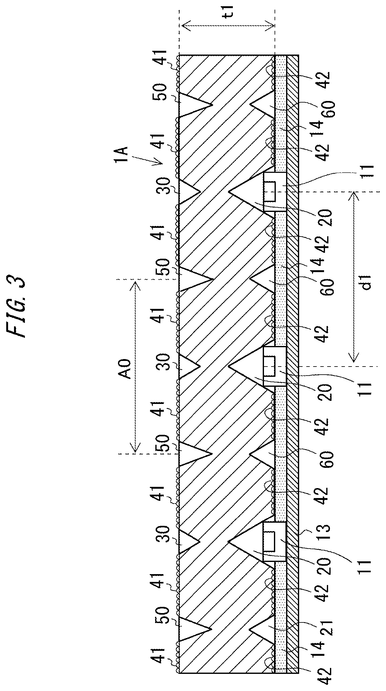
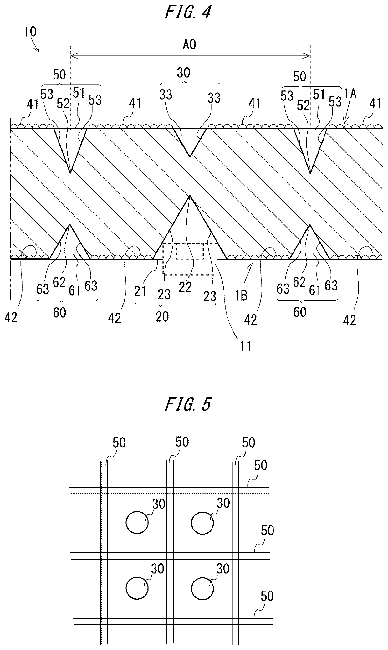
[0051]FIG. 3 is a sectional view of the light guide plate 10. A ratio of sizes of the respective components and the like are not limited to the illustrated example. The light guide plate 10 has a plurality of depressed portions 20 on the lower surface of the light guide plate 10. The depressed portion 20 has a conical shape. The plurality of light sources 11 are arranged on the mounting substrate 13 and one light source 11 is housed inside each depressed portion 20. Light emitted from the light source 11 is incident into the light guide plate 10. Due to light incident into the light guide plate 10 being refracted, reflected, and diffused inside the light guide plate 10 and emitted from a light exit surface 1A of the light guide plate 10, the light exit surface 1A of the light guide plate 10 is uniformly lighted. While a thickness (height) t1 of the light guide plate 10 is, for example, 0.35 mm, the thickness (height) t1 is not limited to this value and may assume another value such ...
second specific example
[0064]FIG. 8 is a sectional view schematically showing a second specific example of the light guide plate 10. In the present specific example, components corresponding to the configuration described above will be assigned corresponding reference numerals and a description thereof will be omitted.
[0065]The light guide plate 10 according to the present specific example is configured so as to be formed by an individual piece for each light source 11 and arranged in a matrix pattern corresponding to the light sources 11.
[0066]The first restricting portion according to the present second specific example is constituted by a side surface 71 of the light guide plate 10 formed as an individual piece. For example, by installing individual pieces of the light guide plate 10 in a row while providing minute gaps between the side surfaces 71 and reflecting light incident to the side surface 71 at angles exceeding the critical angle, traveling, toward the side of the light exit surface outside th...
third specific example
[0071]FIG. 9 is a sectional view schematically showing a third specific example of the light guide plate 10. In the present third specific example, components corresponding to the configurations described above will be assigned corresponding reference numerals and a description thereof will be omitted.
[0072]As shown in FIG. 9, in the present third specific example, a reflective layer 81 is formed on an inner surface of the groove portion 60. By forming a reflective surface on the inclined surface 63 of the groove portion 60 in this manner, light traveling from the inside toward the outside of the illuminated area A0 is reflected toward the inside of the illuminated area A0 when striking the groove portion 60. This configuration restricts traveling, toward the side of the light exit surface outside of the illuminated area A0, of light traveling from the inside toward the outside of the illuminated area A0.
[0073]In addition, FIG. 10 is a diagram showing a modification of the light gui...
PUM
 Abstract
Description
Claims
Application Information
 - R&D
- Intellectual Property
- Life Sciences
- Materials
- Tech Scout
- Unparalleled Data Quality
- Higher Quality Content
- 60% Fewer Hallucinations
Browse by: Latest US Patents, China's latest patents, Technical Efficacy Thesaurus, Application Domain, Technology Topic, Popular Technical Reports.
© 2025 PatSnap. All rights reserved.Legal|Privacy policy|Modern Slavery Act Transparency Statement|Sitemap|About US| Contact US: help@patsnap.com


