
Sunlight-based sun imitating illumination

a projector and sunlight technology, applied in the field of sunlight-based projector systems, can solve the problems of only providing illumination, back scattering and fresnel losses, and additional losses inside the fiber by light absorption, so as to increase the natural illumination condition, increase the energy efficiency, and improve the effect of illumination efficiency

Active Publication Date: 2020-02-20
COELUX
View PDF13 Cites 12 Cited by
  • Summary
  • Abstract
  • Description
  • Claims
  • Application Information

AI Technical Summary

Benefits of technology

The patent text explains that using sun-sky imitating illumination systems can provide energy-efficient illumination of indoor environments while still giving the impression of infinite depth perception. This is especially true during the day, but also applies to other times like morning and afternoon, as well as cloudy days. Overall, the system helps to make indoor environments brighter and more energy-efficient.

Problems solved by technology

Losses are primarily generated by interfaces, each creating back scattering and Fresnel losses.
Additional losses are created inside the fiber by light absorption.
Clearly, systems based on passive emitters only provide illumination when adequate natural light is collected by the collector optics.

Method used


Image

  • Sunlight-based sun imitating illumination
  • Sunlight-based sun imitating illumination
  • Sunlight-based sun imitating illumination

Examples


Embodiment Construction

[0031]The following is a detailed description of exemplary embodiments of the present disclosure. The exemplary embodiments described therein and illustrated in the drawings are intended to teach the principles of the present disclosure, enabling those of ordinary skill in the art to implement and use the present disclosure in many different environments and for many different applications. Therefore, the exemplary embodiments are not intended to be, and should not be considered as, a limiting description of the scope of patent protection. Rather, the scope of patent protection shall be defined by the appended claims.

[0032]The disclosure is based in part on the realization that collected daylight may be used to provide indoor natural lighting conditions. For that purpose, it was realized that light providing units of daylight-based illumination systems can be used to provide collimated sun-like light uniformly emitted from a large area. Specifically, it was realized that the emitted...


PUM


Abstract

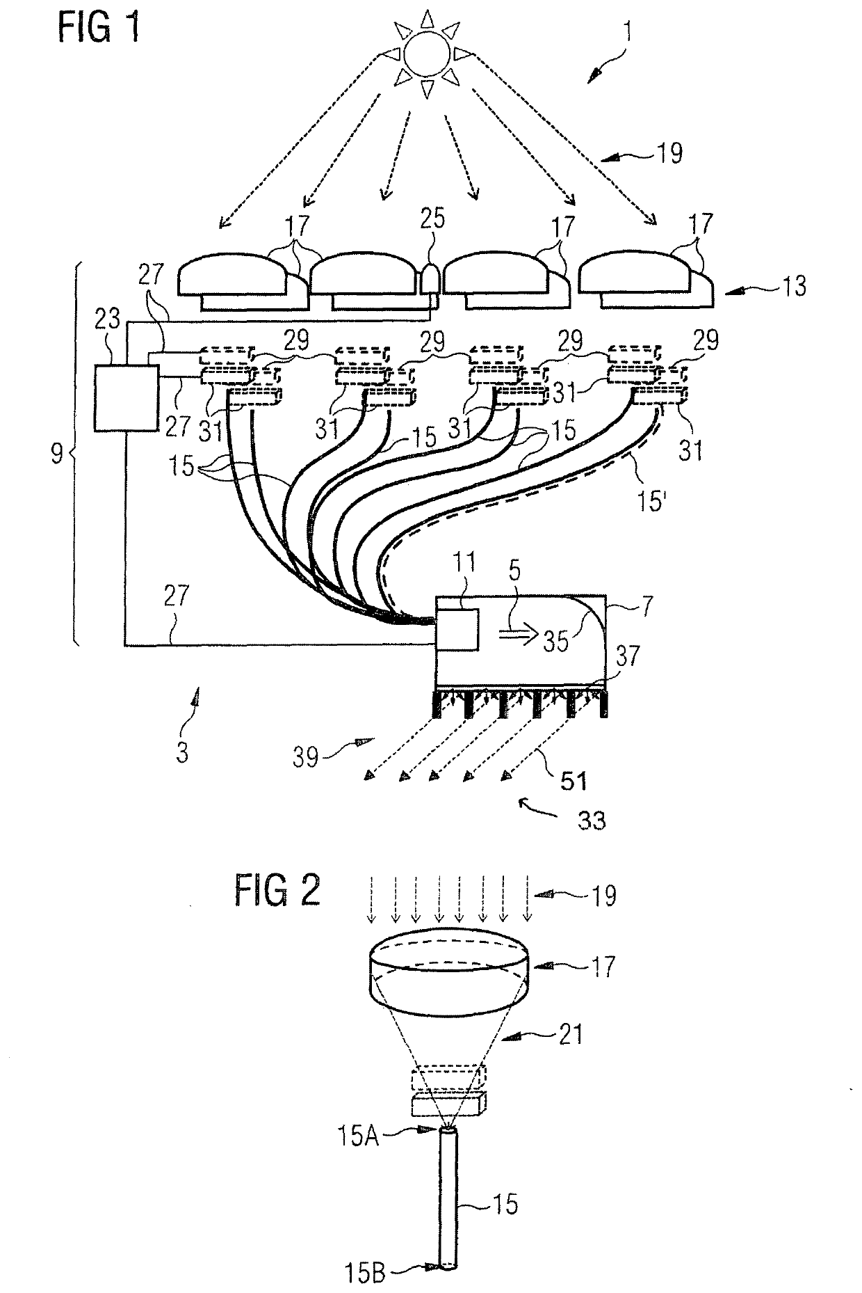
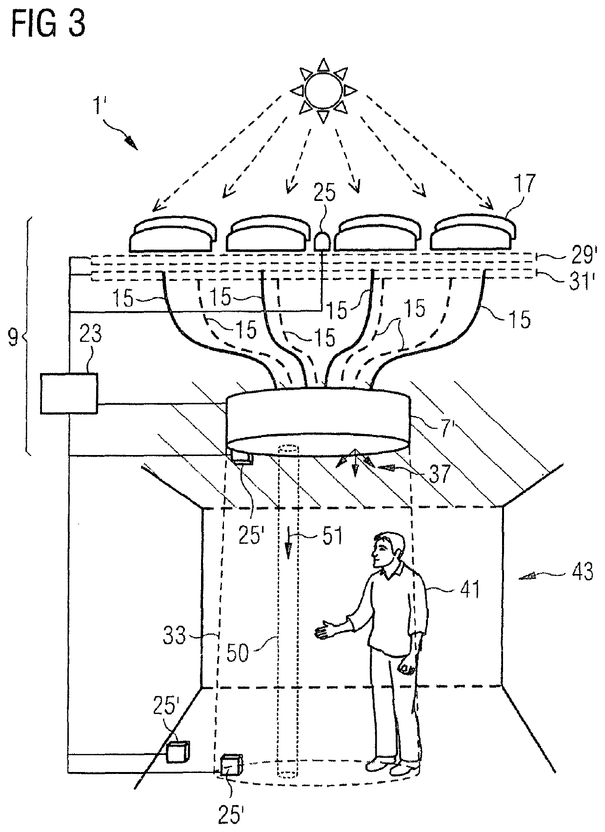
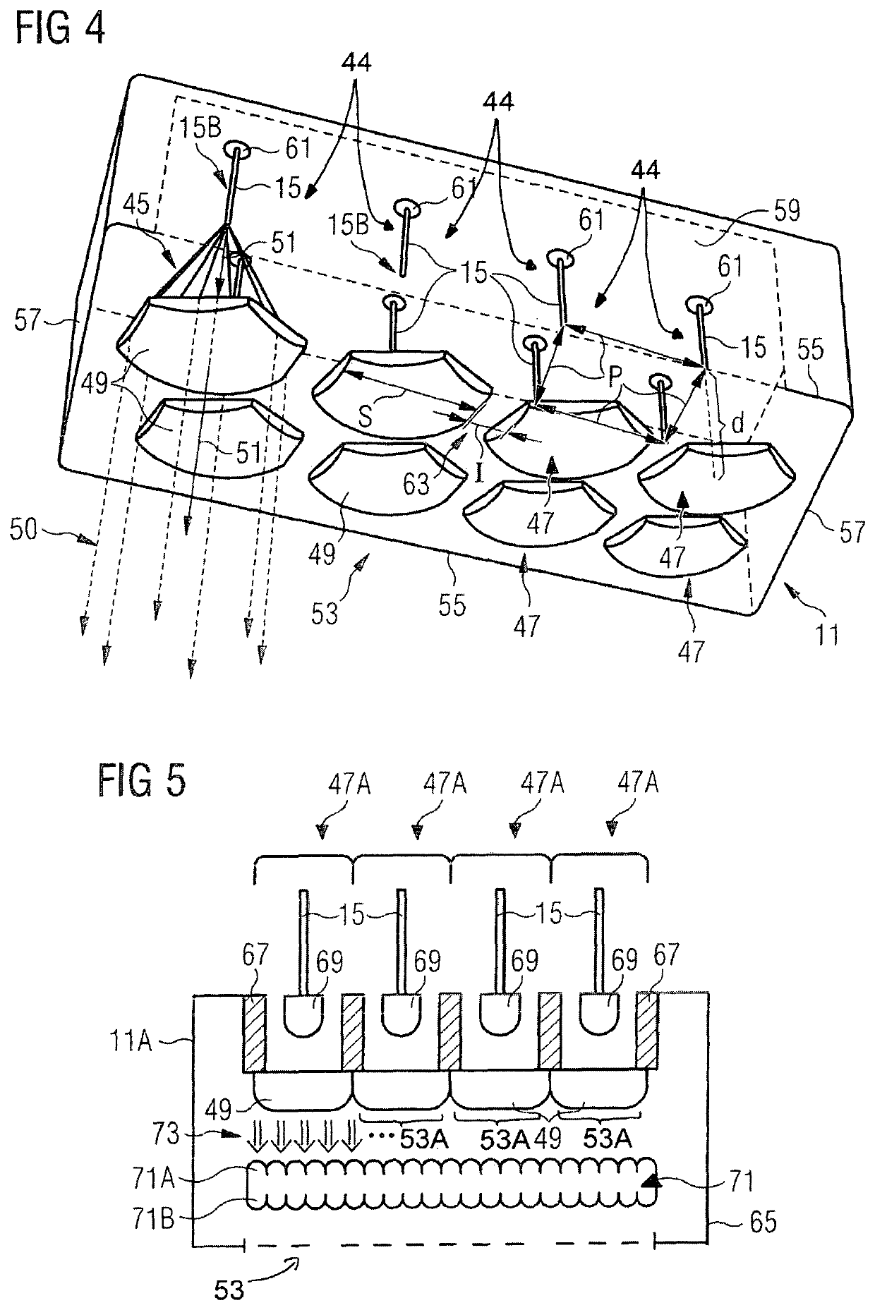
A sunlight-based projector system (3) is disclosed for providing a direct light beam (5). The projector system (3) comprises a sunlight receiving unit (9) with a collector system (13), a plurality of optical fibers (15), and a plurality of fiber output channels (44). The collector system (13) collects natural outdoor light, and couples the collected light into the plurality of optical fibers (15). The projector system (3) comprises further a sunlight forming unit (11) with a plurality of optical collimator units (47) arranged in a two-dimensional array, wherein each optical collimator unit (47) receives the respective fiber output light (45) and comprises at least one optical collimator (49) for reducing the angular distribution width of the received divergent fiber output light (45). Output areas of the plurality of optical collimator units (47) form essentially a continuously extending large light-emitting face (53) of the sunlight forming unit (11) for emitting an essentially collimated light beam (5). The generated direct light beam (5) may be used together with diffused light generating areal units to provide a sun-sky imitating lighting system with a sun-like appearance.

Description

TECHNICAL FIELD[0001]The present disclosure relates generally to sunlight-based projector system and in particular to lighting systems using natural light for indoor illumination. Moreover, the present disclosure relates to controlling sunlight-based lighting systems and to supplementing sunlight-based lighting systems with artificial light.BACKGROUND[0002]Daylight-based illumination systems collect daylight and guide the collected light in particular by optic systems to luminaires that are distributed within a building. Accordingly, daylight-based illumination systems are energy efficient and allow the illumination of an indoor ambience with light having a natural visible spectrum.[0003]Commercially available products include lens-based or reflector-based collector optics, a tracking system for following the sun-movement with the collector optics, a fiber-based light distribution system, and indoor light providing units. Daylight based illumination systems are disclosed, for exampl...

Claims


Application Information

Patent Timeline
IPC IPC(8): F21S11/00F21V9/02G02B3/00G02B5/00F21V14/08F21V3/04F21S19/00F21V23/04F21V23/00F21V5/00F21V8/00
CPCF21S11/002G02B6/0008F21V14/08G02B5/003F21Y2115/10F21V9/02F21S19/005G02B3/0062F21Y2113/13F21V23/003F21V5/008F21S11/007G02B3/0056G02B2207/101F21V3/049F21V23/0464F21V23/0442
Inventor DI TRAPANI, PAOLOMAGATTI, DAVIDEMOLTENI, MATTEO
Owner COELUX
Learn More