
Method to control a virtual image in a display

a virtual image and display technology, applied in the field of mirror optics, can solve the problems of difficult integration of high-resolution and high-quality displays, limited determination of the location of virtual images for non-planar mirrors or lenses, and the conflict between depth cues of virtual reality displays

Active Publication Date: 2020-02-20
8259402 CANADA INC
View PDF9 Cites 5 Cited by
  • Summary
  • Abstract
  • Description
  • Claims
  • Application Information

AI Technical Summary

Benefits of technology

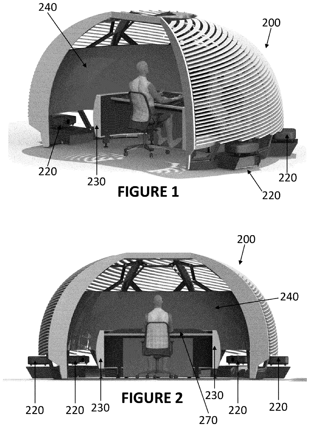
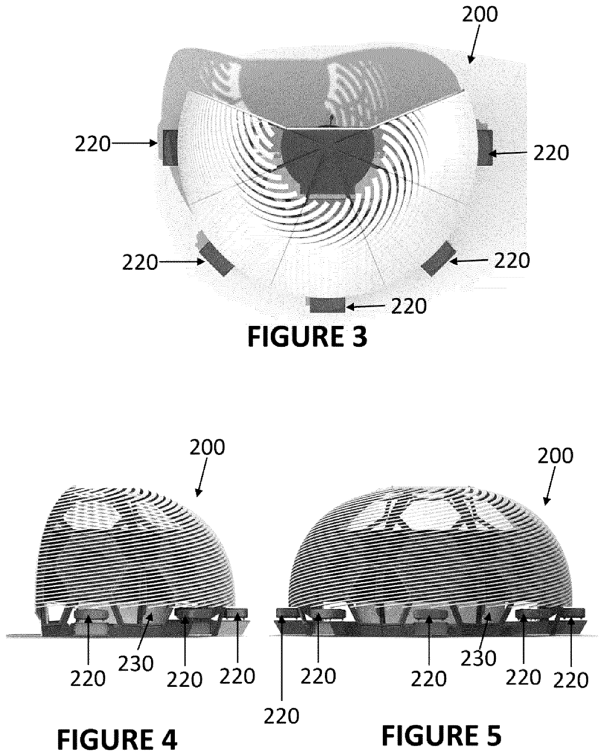
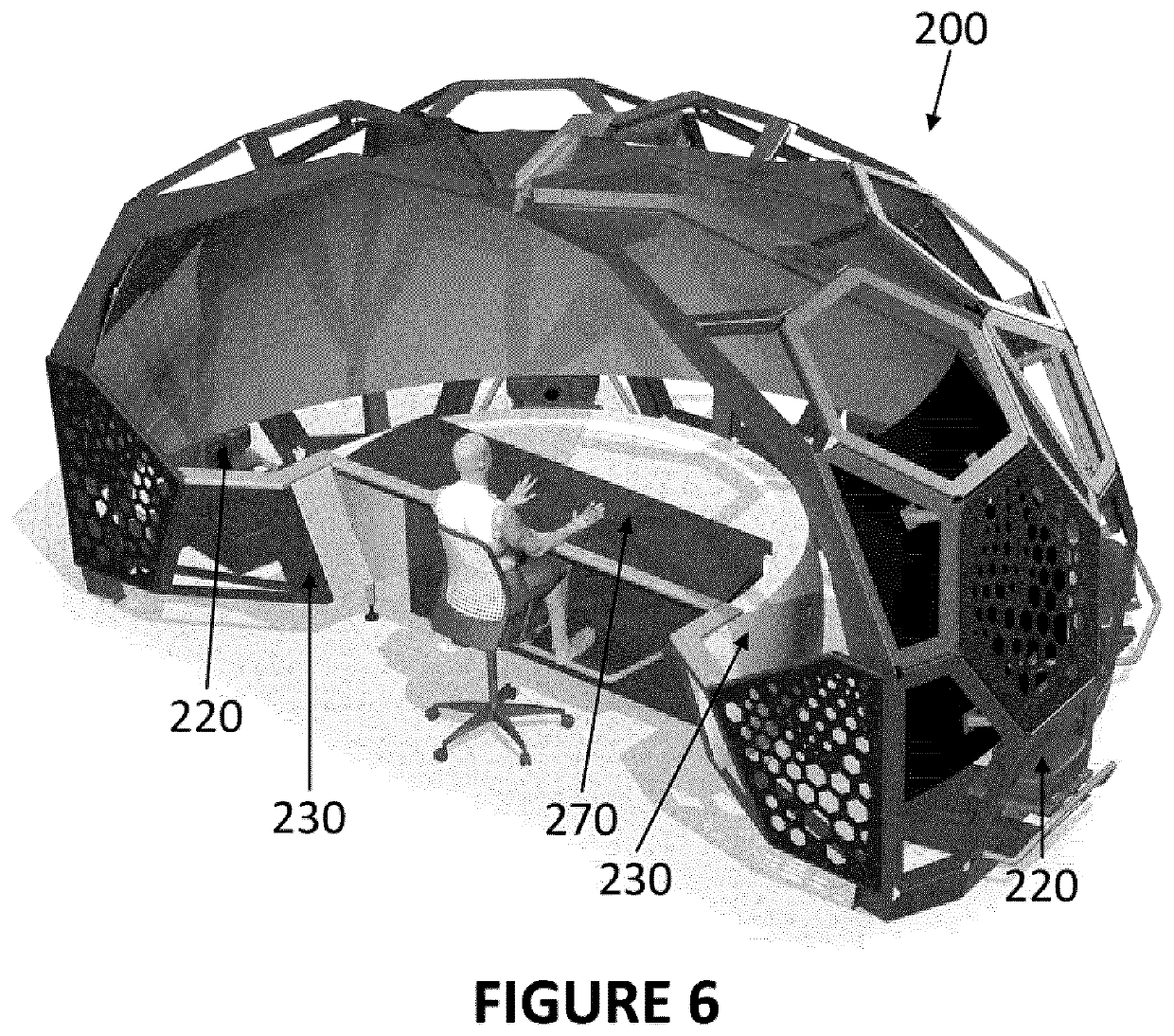
The patent describes a method for controlling a virtual image of a displaying object in a display. The method involves determining the shape of the display screen or the object on which the virtual image is displayed, and then using this shape to create a virtual image that provides parallax and a stereoscopic depth cue for the observer viewing the object through a curved mirrored surface. The virtual image can be controlled by adjusting the images displayed on the screen or the object using a computing system. The technical effect of this method is that it allows for a more immersive and realistic virtual image experience for the observer.

Problems solved by technology

Current standard methods for determining the location of a virtual image for non-planar mirrors or lenses are limited in two ways:1) they are based on Gaussian optics, and therefore are only valid when both the observer and the object are near the optical axis of the lens or mirror, and / or2) they do not account for the different, conflicting depth cues used by a human observer to infer depth.
However, the user is required to wear the HMD at all times to enjoy the immersive content, a situation that is not always desirable, especially if the user is to be immersed for long periods, e.g., for training in a flight simulator or for working in an immersive work station.
Consequently, it is hard to incorporate high-resolution and high-quality displays.
Virtual reality displays also suffer from the depth cue conflicts such as the vergence-accommodation conflict, i.e., the distance at which a viewer focuses their eyes to see the image clearly is not consistent with the distance they perceive the image via stereoscopic cues.
Virtual reality displays also have problems with motion sickness.
Although relatively simple to install and convenient for many purposes, such as watching movies, these displays suffer from an unrealistic depth sensation, since images are projected onto a screen having a fixed distance to the viewers, and therefore the viewer is not completely immersed into the experience since there is no depth differentiation between objects in the image.
This can, however, be uncomfortable (especially for long-time use or for users already wearing glasses) and create a lack of realism since glasses need to be worn to reproduce a reality where no glasses would ordinarily be worn.
These displays also suffer from the vergence-accommodation conflict.
Current standard methods for determining the location of a virtual image for non-planar mirrors or lenses are limited in two ways: they are based on Gaussian optics, and hence are only valid when both the observer and object are near the optical axis of the lens or mirror, and / or they do not account for the different, conflicting depth cues used by a human observer to infer depth.
This does not allow a proper sense of depth when objects in the content being viewed are supposed to be located at a distance closer than this distance.

Method used


Image

  • Method to control a virtual image in a display
  • Method to control a virtual image in a display
  • Method to control a virtual image in a display

Examples


experimental verification

[0162]These results were verified by experimentally measuring the depth of image points reflecting from a mirrored surface using two cameras.

[0163]A silver-coated hemisphere made of acrylic with a diameter of 18″ in diameter was used as the hemispherical mirror. A 55″ LG OLED HD television was placed 15 mm above this hemisphere, and two Point Grey BlackFly cameras were placed and mounted on an optics table 686 mm from the hemisphere's center. A custom part was used to keep the cameras at a separation of 54 mm and to ensure the cameras were directed parallel to one another.

[0164]FIG. 19 shows stereoscopic measurements for pinhole cameras. The distance of objects relative to the two cameras were determined via triangulation, based on a technique often used in computer vision. Based on the distance between the two cameras, B, the focal length of the cameras, fL and fR, and the measured location of the object in the two images, xL and xR, the depths were determined using the following f...


PUM


Abstract

There is described a method for controlling, in a display, a virtual image of a displaying object for which displaying is controllable. The method comprises providing a curved mirrored surface opposing the displaying object to produce the virtual image. The location of an observer is determined, with respect to the curved mirrored surface. A position of the virtual image can then be determined for the observer at the location, wherein this virtual image provides at least one of parallax and a stereoscopic depth cue. The displaying object is controlled to produce the virtual image as determined.

Description

CROSS-REFERENCE TO RELATED APPLICATIONS[0001]This application claims priority or benefit of U.S. provisional patent application 62 / 467,846 filed Mar. 7, 2017 and of U.S. provisional patent application 62 / 514,194 filed Jun. 2, 2017, the specifications of which are hereby incorporated herein by reference in their entirety.BACKGROUND(a) Field[0002]The subject matter disclosed generally relates to mirror optics. More specifically, it relates to the use of mirrored surfaces for display applications.(b) Related Prior Art[0003]The image of an object formed from the reflection of light rays from a mirrored surface is known as the virtual image of the object. Current standard methods for determining the location of a virtual image for non-planar mirrors or lenses are limited in two ways:[0004]1) they are based on Gaussian optics, and therefore are only valid when both the observer and the object are near the optical axis of the lens or mirror, and / or[0005]2) they do not account for the diffe...

Claims


Application Information

Patent Timeline
Patent Type & Authority Applications(United States)
IPC IPC(8): G02B27/22G09G3/00G02B30/26
CPCG02B30/26G02B30/35G09G2380/12G09G2354/00G09G2340/0464G09G2320/0261G09G3/003G09B9/32G02B27/0093H04N13/117G02B27/0172G02B2027/0185G06T19/006G06F3/011H04N13/10H04N13/128G02B5/10G02B27/0101
Inventor RADEL, JASON CARLPETRUZZIELLO, FERNANDO
Owner 8259402 CANADA INC
Learn More