Direction of arrival estimation for automotive spread radar systems

a spread radar and direction of arrival technology, applied in the direction of reradiation, measurement devices, instruments, etc., can solve problems such as ambiguity in angular reconstruction, and achieve the effect of fast modification of method steps and robust and reliable execution of methods

Active Publication Date: 2020-02-27
IEE INT ELECTRONICS & ENG SA
View PDF3 Cites 7 Cited by
  • Summary
  • Abstract
  • Description
  • Claims
  • Application Information

AI Technical Summary

Benefits of technology

[0034]The software module can enable a robust and reliable execution of the method and can allow for a fast modification of method steps.

Problems solved by technology

In automotive radar applications one challenge is to determine the Direction of Arrival (DoA) of incoming radar waves which were transmitted towards and were reflected by targets.
Further, a displacement of the antennas by multiple wavelengths leads to ambiguity in angular reconstruction when performed with conventional DBF.

Method used


Image

  • Direction of arrival estimation for automotive spread radar systems
  • Direction of arrival estimation for automotive spread radar systems
  • Direction of arrival estimation for automotive spread radar systems

Examples


Embodiment Construction

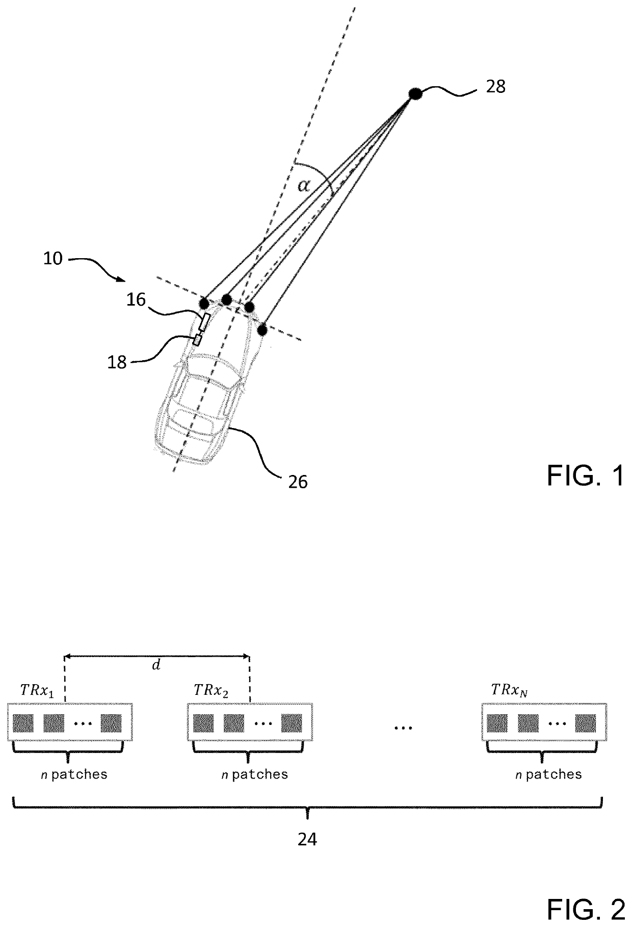
[0052]FIG. 1 shows a possible embodiment of an automotive spread radar system 10 for direction of arrival estimation of radar waves reflected by a target 28 in accordance with the invention. The automotive spread radar system 10 is installed in a vehicle 26 formed by a passenger car to provide information that is to be used as an input for a collision avoidance system of the vehicle 26. The automotive spread radar system 10 comprises a plurality of N=4 transceiver antenna units TRxk, k=1−N, that are arranged at a priori known positions at a front region of the vehicle 26.

[0053]FIG. 2 schematically illustrates the plurality of N=4 transceiver antenna units TRxk, k=1−N, of the automotive spread radar system 10 pursuant to FIG. 1. In FIG. 2, the transceiver antenna units TRxk are shown to be arranged at a priori known positions to form a one-dimensioned linear array 24, wherein the transceiver antenna units TRxk are evenly spaced by a distance d, for example 0.5 m. For reasons of simpl...


PUM


Abstract

A method of direction of arrival estimation with an automotive spread radar system. The automotive spread radar system includes a plurality of at least two transceiver antenna units, which are configured to work in a MIMO configuration, wherein the transceiver antenna units are arranged at a priori known positions. The automotive spread radar system is configured to determine, for each transceiver unit antenna unit of the plurality of transceiver antenna units, a range of a target reflecting radar waves that have been transmitted by at least the specific transceiver antenna unit by reading out a plurality of range gates assigned to a specific transceiver antenna unit. The method and radar system are capable of estimating a direction of arrival without the need of ensuring a synchronization of antennas on the scale of a radar carrier frequency.

Description

TECHNICAL FIELD[0001]The invention generally relates to a method of direction of arrival estimation with an automotive spread radar system, an automotive spread radar system configured for estimating a direction of arrival, and a software module for controlling automatic execution of the method.BACKGROUND OF THE INVENTION[0002]It is known in the art to employ radar technology, in particular in the millimeter wave range between 75 and 81 GHz, in exterior automotive applications such as driver assistance systems for providing improved safety by facilitating an optimized reaction of a driver of a vehicle with appropriate warnings or even by automatically taking over control of the vehicle, for instance in collision avoidance systems.[0003]In automotive radar applications one challenge is to determine the Direction of Arrival (DoA) of incoming radar waves which were transmitted towards and were reflected by targets. Common realizations deal with large patch antennas and beamforming algo...

Claims


Application Information

Patent Timeline
Patent Type & Authority Applications(United States)
IPC IPC(8): G01S13/00G01S13/36G01S13/93G01S13/931
CPCG01S2013/93271G01S13/36G01S13/931G01S2013/466G01S13/003G01S13/18G01S13/325G01S13/34G01S13/878
Inventor SCHRODER, UDOBEISE, HANS-PETERSTIFTER, THOMAS
Owner IEE INT ELECTRONICS & ENG SA
Why Eureka
Try Eureka