
Anti-Theft Carrying Straps

a technology of carrying straps and security panels, which is applied in the field of carrying bags, can solve the problems of bag theft or attempted theft, unattended carrying bags are prime targets for potential theft, and owners may be inattention or distracted, and achieves the effects of convenient and comparatively inexpensive assembly, light and flexible, and non-bulky configuration

Inactive Publication Date: 2020-03-05
TRAVEL CADDY
View PDF0 Cites 0 Cited by
  • Summary
  • Abstract
  • Description
  • Claims
  • Application Information

AI Technical Summary

Benefits of technology

The patent provides new types of carrying bags and straps that are resistant to cutting and scratching, which are easy and inexpensive to make, and are comfortable to wear. These new features also include anti-theft features to prevent theft and unauthorized access to the bag's contents. Overall, the patent presents a way to make carrying bags and straps that are both durable and flexible, which appeal to consumers while maintaining a unique design.

Problems solved by technology

On occasion, such bags are subject to theft or attempted theft.
In such circumstances, a person's attention is often on their activities, and the carrying bag is not being observed at all or most times, and such an unattended carrying bag is a prime target for potential theft.
In other circumstances, the owner of the bag may be inattentive or distracted, such as intentionally distracted by groups or teams of thieves or pickpockets.
While the bag is unattended or the attention of the owner is diverted, moreover, a potential thief typically has considerably more time in which to attempt to gain access to the contents of the bag, especially compared with the much more rapidly occurring grabbing, pickpocketing or slashing of a carrying bag.

Method used


Image

  • Anti-Theft Carrying Straps
  • Anti-Theft Carrying Straps
  • Anti-Theft Carrying Straps

Examples


first embodiment

[0148]Referring to FIGS. 9-11, the routing of a nonmetallic, cut-resistant yarn or fiber 110, 112, 114, or 116 on the first material layer 406 forms a polymeric fiber matrix 125 for a security panel assembly 100A, in which the nonmetallic, cut-resistant yarn or fiber 110, 112, 114, or 116 has a plurality of intersections (or crossings) 138. The nonmetallic, cut-resistant yarn or fiber 110, 112, 114, or 116 is routed over the first material layer 406 (which also may have or be coated with an adhesive or cement 132) around the various pegs 410 in a predetermined pattern to form a polymeric fiber matrix 125. It should be noted that the polymeric fiber matrix 125 spans a larger area than the first material layer 406, resulting in portions or loops 120 of the nonmetallic, cut-resistant yarn or fiber 110, 112, 114, or 116 extending beyond one or more edges 122, 124, 126, and / or 128 of the first material layer 406. As discussed below, the security panel assembly 100 formed this way does no...

seventh embodiment

[0161]FIGS. 25-30 are plan views illustrating a security panel assembly 100G formed from a first flexible material (or material layer) 406 having knit, woven, or spun cut-resistant, polymeric fibers, filaments, cables, threads or yarns 110, 112, 114, or 116 forming a polymeric fiber matrix 125, such as a cut-resistant fabric 200, which is coupled to one or more second flexible materials (or material layers) 408, which is generally not cut-resistant and otherwise is not required to include any polymeric fiber matrix 125 having cut-resistant, polymeric fibers, filaments, cables, threads or yarns 110, 112, 114, or 116. The one or more second flexible materials (or material layers) 408 may be secured to a first flexible material (or material layer) 406 having knit, woven, or spun cut-resistant, polymeric fibers, filaments, cables, threads or yarns 110, 112, 114, or 116 forming a polymeric fiber matrix 125, such as through stitching 415 or an adhesive 132 (not separately illustrated), to...

eighth embodiment

[0170]FIGS. 31-33 are plan views illustrating a security panel assembly 100H formed from a plurality of first flexible materials (or material layers) 406 having knit, woven, or spun cut-resistant, polymeric fibers, filaments, cables, threads or yarns 110, 112, 114, or 116 forming a polymeric fiber matrix 125, such as a cut-resistant fabric 200, which is coupled to at least one second flexible material (or material layer) 408, which is generally not cut-resistant and otherwise is not required to include any polymeric fiber matrix 125 having cut-resistant, polymeric fibers, filaments, cables, threads or yarns 110, 112, 114, or 116. The one or more first flexible materials (or material layers) 406 having knit, woven, or spun cut-resistant, polymeric fibers, filaments, cables, threads or yarns 110, 112, 114, or 116 forming a polymeric fiber matrix 125, may be secured to a second flexible material (or material layer) 408 such as through stitching 415 or an adhesive 132 (not separately il...


PUM

PropertyMeasurementUnit
molecular massaaaaaaaaaa
lengthaaaaaaaaaa

Abstract

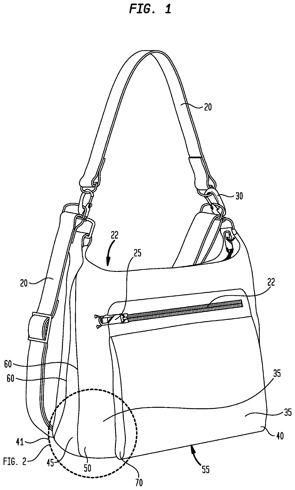
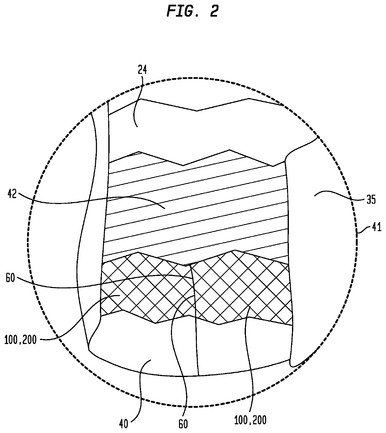
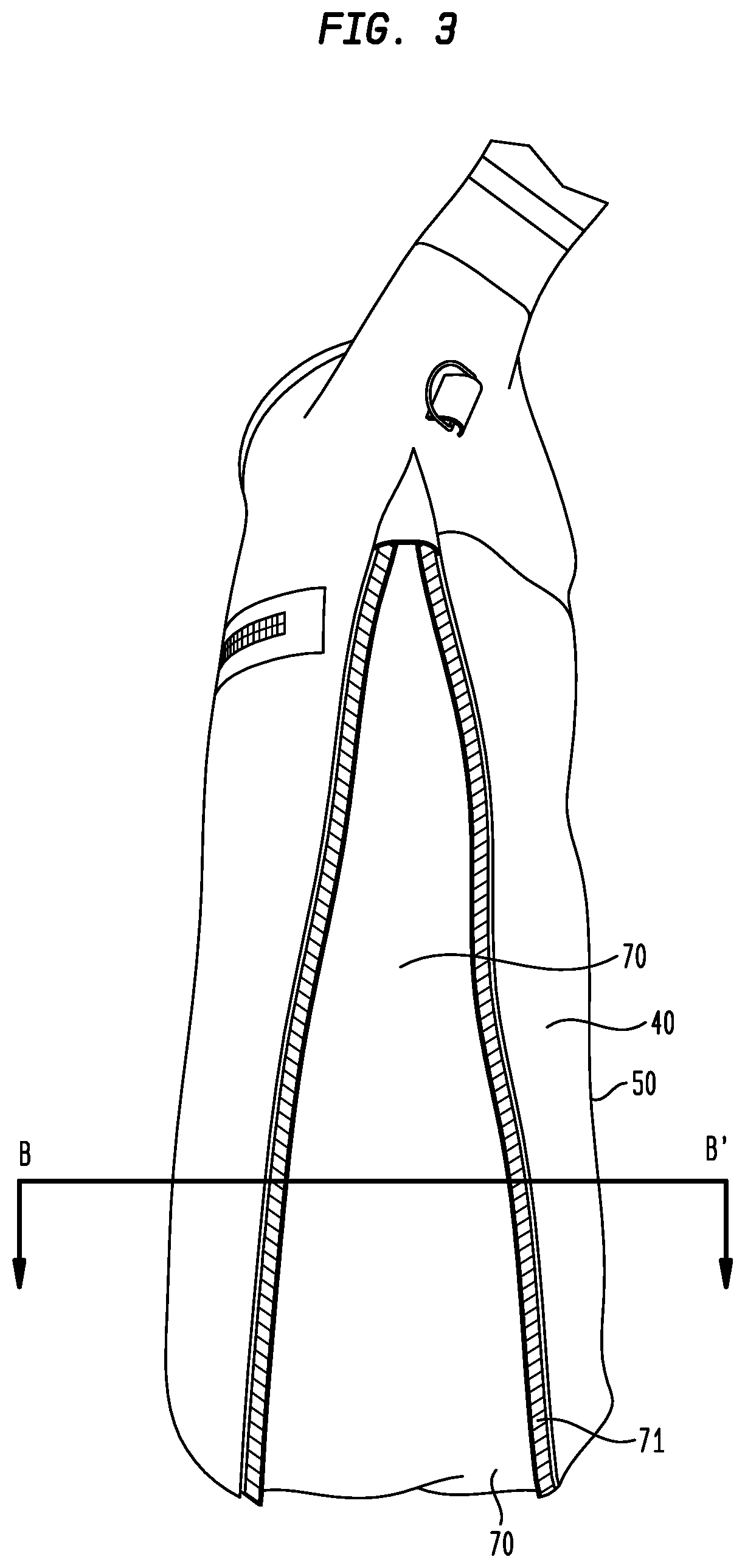
In various embodiments, a carrying bag is disclosed which includes a one or more security panel assemblies comprising a first flexible material layer and a polymeric fiber matrix, such as a polymer fiber-based cut-resistant fabric, matrix or mesh. Various carrying straps are disclosed which include a first flexible fabric or webbing; and a second flexible fabric or webbing comprising a polymeric fiber matrix. Additional polymeric fibers, filaments, cables, threads or yarns may be included in the security panel assemblies and straps, such as cut-resistant monofilament and multifilament fibers comprised of a polyethylene such as ultra high molecular weight polyethylene (UHMWPE), high-modulus polyethylene (HMPE), or High Performance Polyethylene (HPPE), for example.

Description

CROSS-REFERENCE TO A RELATED APPLICATION[0001]This application is nonprovisional of and claims priority to and the benefit of U.S. Provisional Patent Application No. 62 / 695,994, filed Jul. 10, 2018, inventors Donald E. Godshaw et al., titled “Anti-Theft Carrying Bags and Carrying Straps”, which is commonly assigned herewith, the entire contents of which are incorporated herein by reference with the same full force and effect as if set forth in its entirety herein, and with priority claimed for all commonly disclosed subject matter.FIELD OF THE INVENTION[0002]This invention relates to various types of carrying bags and, more particularly, to a cut or slash-resistant carrying bag with a cut or slash-resistant security panel for carrying bags such as purses, backpacks, messenger bags, briefcases, luggage, and so on, and to cut or slash-resistant carrying straps which may be used with such carrying bags.BACKGROUND OF THE INVENTION[0003]Handbags, travel bags, purses, backpacks, messenger...

Claims


Application Information

Patent Timeline
Patent Type & Authority Applications(United States)
IPC IPC(8): B32B5/26A45C3/00A45C3/06A45C13/18B32B5/02B32B7/09A45C13/30B32B7/12
CPCB32B7/12A45C3/06B32B2262/02B32B2262/0253B32B7/09B32B2262/0276A45C13/30B32B5/026B32B2307/581A45C3/001B32B5/024B32B2439/00A45C13/18B32B5/26B32B2262/101A45C2003/002A45C7/0068A45C13/36A45F3/04A45C13/02
Inventor GODSHAW, DONALD E.KRAMER, JASON MICHAELHICKMAN, BRYCE RYANHAI, DUREEVES, MALEASCOTT, JACLYN
Owner TRAVEL CADDY
Learn More