Multi-layer film

a film and multi-layer technology, applied in the field of multi-layer film, can solve the problems of increasing the amount of dust and the possibility of generating dust, significant damage to the film, and damage to the clear material base sheet, and achieve the effect of facilitating the slitting process

Inactive Publication Date: 2020-03-05
MASE RYOICHI
View PDF0 Cites 0 Cited by
  • Summary
  • Abstract
  • Description
  • Claims
  • Application Information

AI Technical Summary

Benefits of technology

[0011]The present invention was made to eliminate the above-identified problems. Therefore, an object of this invention is to provide a multi-layer film showing a sufficient scratch resistant property on the outward facing film, having a clear material base sheet, an adhesive layer applied on a back surface of the clear material base sheet, and a separator temporarily placed and adhered on the adhesive layer, where the separator has a strong tear directionality in one direction allowing the user to tear the separator cleanly and in a straight line and after the separator is torn and removed it exposes a section of the adhesive layer whereafter the user can accurately and easily position the clear material base sheet on the device display. It is another object of this invention to enable the user to tear the predetermined portion of the film cleanly and almost straight without the risk of bubble and white line formation problems.
[0016]The multi-layer film A of this invention has the separator 30 with strong tear directionality and a slit S in the tear direction, allowing the user to tear the separator in a nearly straight line, and this clean, straight tearability facilitates and simplifies the positioning and installation process of the film on the display. During the manufacturing and forming process of the slit S on the film A, slitting all the way crossing the separator as in the conventional art using the blade is not necessary, which eliminates a chance of damaging the film sheet by the blade extending into undesirable areas of the adhesive layer or the clear material base sheet.
[0018]The clear material base sheet 10 can be designed smaller than the separator, and at least one slit S can be formed on a portion of the separator not superposing the clear material base sheet 10, thereby removing the above-identified problems with the knife and cutting.
[0019]Alternatively, the clear material base sheet 10 has an effective area which is actually used as a film and a disposable area which can be disposed after installation of the film on the display. In this case, the slit S can be made in the disposable area and the cut can extend to the clear material base sheet 10, which makes the blade slitting process much easier.

Problems solved by technology

The conventional multi-layer film A has a problem of being positioned on the display because the user needs to guess an appropriate position after removing the separator or as gradually removing the separator.
However, this approximately half-slit separator has a problem of generating cutting dust that ultimately ends up on the adhesive layer 20, and the amount of the dust and the possibility of generating the dust increases as the half-slit line becomes longer.
Furthermore, during the slitting process the blade may accidentally cut deeper, causing a damage to the clear material base sheet 10.
In an extreme situation, the blade extends further to slightly cut the entire cross line of the film A possibly causing significant damage to the film A.

Method used


Image

  • Multi-layer film
  • Multi-layer film
  • Multi-layer film

Examples


first embodiment

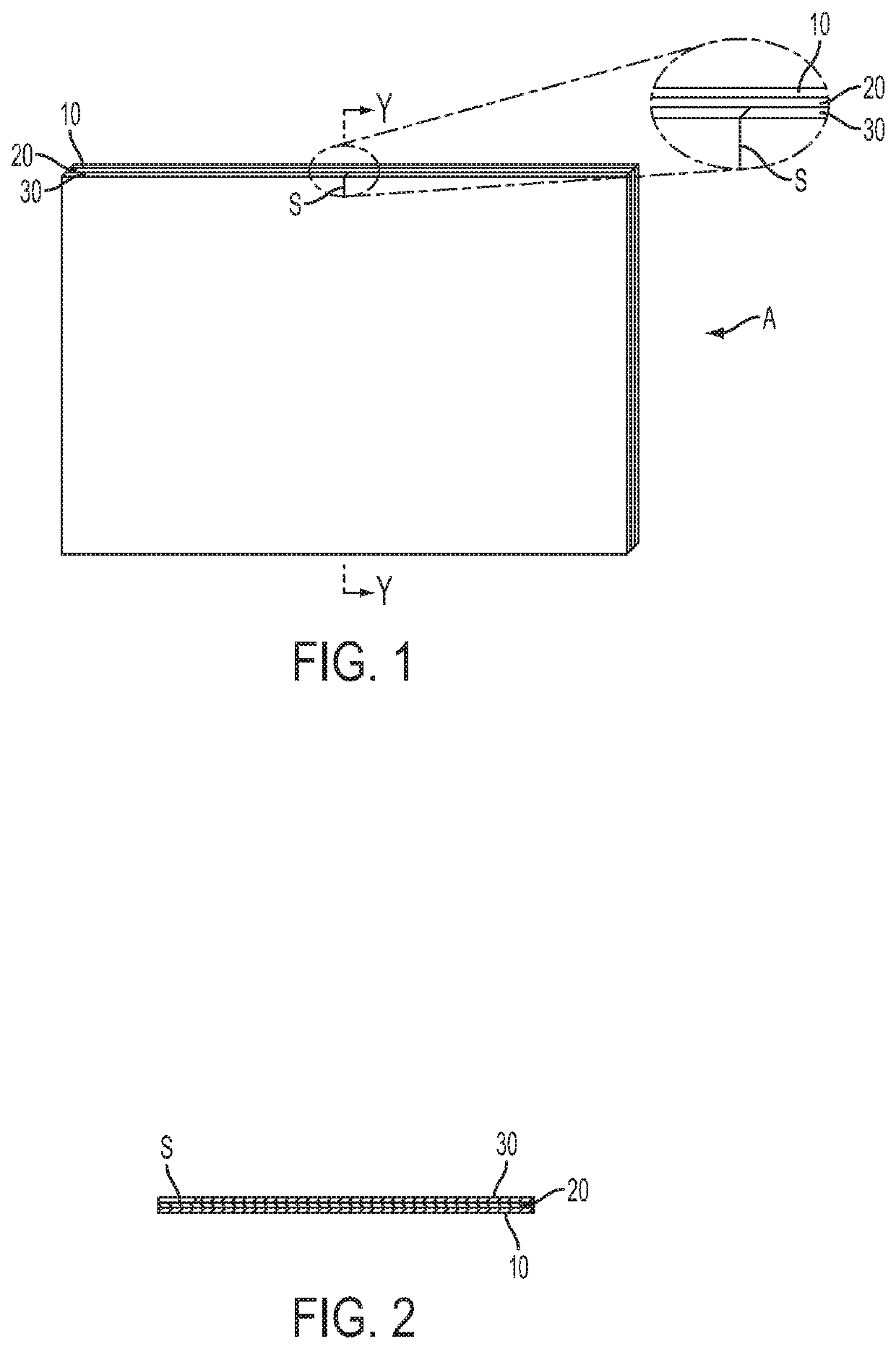
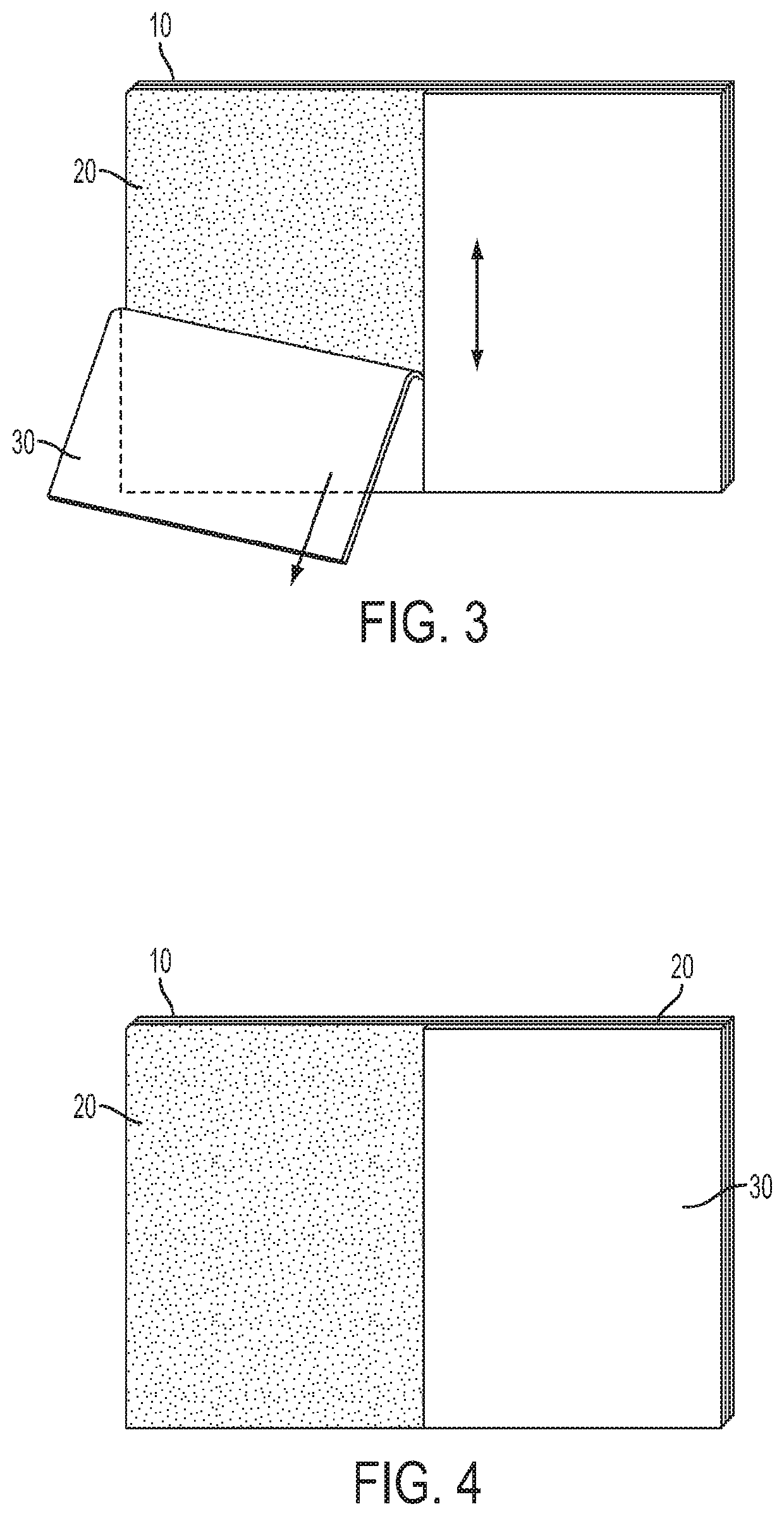
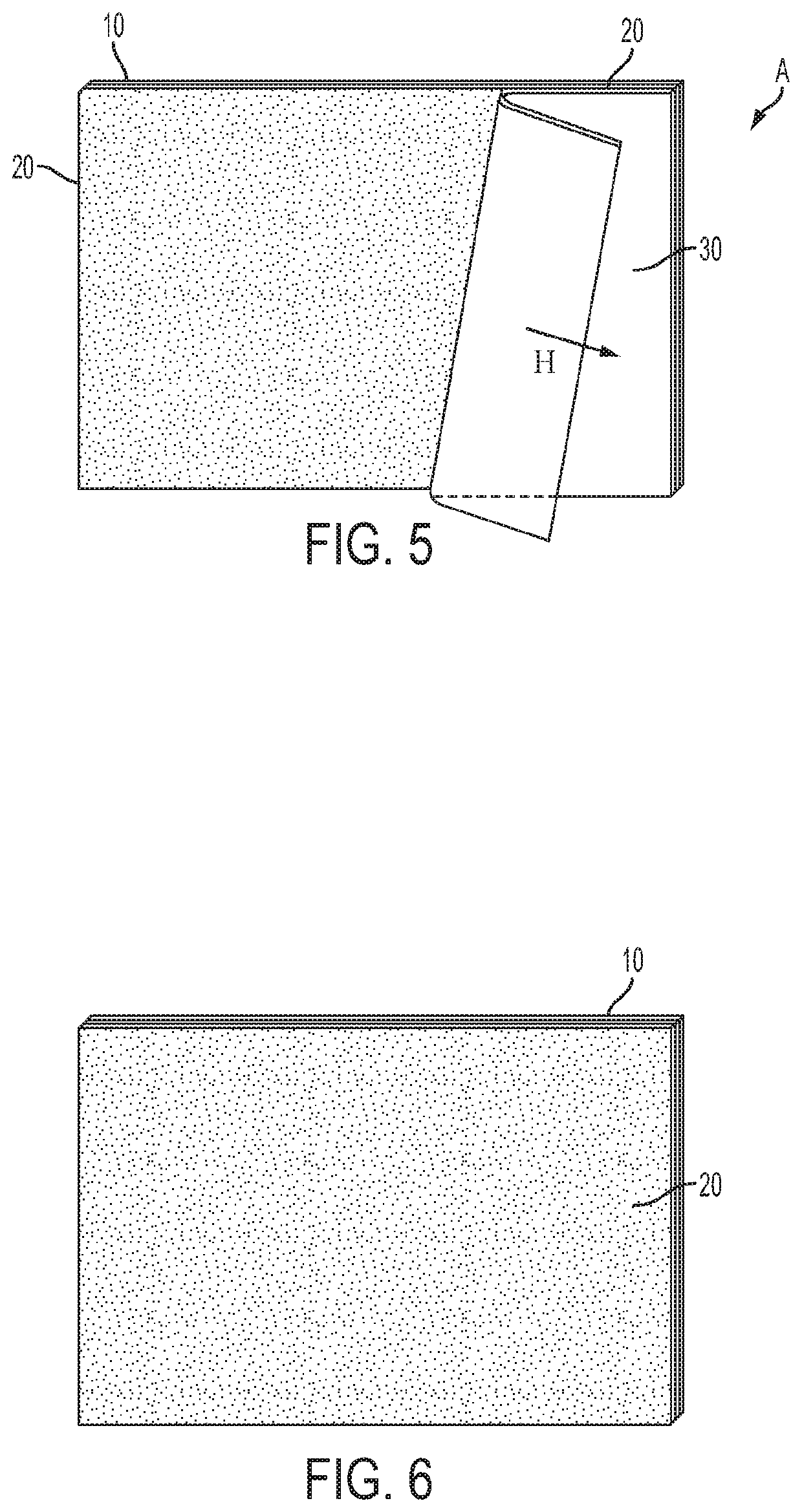
[0049]FIG. 1 is a perspective view of the multi-layer film A according to the first embodiment of this invention, and FIG. 2 is a cross section view of the multi-layer film A of the first embodiment taken along the line Y-Y;

[0050]The multi-layer film A according to this embodiment is a rectangular film having a clear material base sheet 10, an adhesive layer 20, and a separator 30.

[0051]This multi-layer film is structured so that a front surface of the clear material base sheet 10 is exposed to the user and this front surface has scratch resistant properties so as to protect the film surface when used by the user, the adhesive layer 20 is created on a back surface of the clear material base sheet 10, and the separator 30 is temporarily placed and attached to the adhesive layer 20.

[0052]The clear material base sheet 10 for example can be an entirely clear material, it can be a reflection sheet, a polarizing sheet, a clear sheet with decoration, a semi-transparent sheet, a phase diffe...

second embodiment

[0068]FIG. 7 is a perspective view of the multi-layer film A according to the second embodiment of this invention, and FIG. 8 is a cross section view of the multi-layer film A of the second embodiment taken along the line Y-Y.

[0069]The multi-layer film sheet A of the second embodiment has the slit S in an intermediate portion of the separator 30, as in the first embodiment, but the slit S is deeper than the slit S in the first embodiment so that it goes into the adhesive layer 20. Although the slit S is short and should stop at the adhesive layer 20, the quality of the film A after completion of the installation would not be affected even if the blade accidentally goes into the clear material base sheet 10. The installation process is the same as the first embodiment and the explanation of which will be omitted here.

third embodiment

[0070]FIG. 9 is a perspective view of the multi-layer film A according to the third embodiment of this invention, and FIG. 10 is a cross section view of the multi-layer film A of the third embodiment taken along the line Y-Y. The multi-layer film A of the third embodiment has an effective area P1 which is installed on the electronic device display and a disposable area P2 which can be disposed after installing the film on the display. The effective area P1 is a film placed on the display and the disposable area P2 is disposed after tearing and separating from the effective area P1. A detach line D is formed on the clear material base sheet 10 and the adhesive layer 20 between the effective area P1 and the adjacent disposable area P2. The disposable area P2 can be in any shape but in this embodiment the disposable area P2 has the same width along the detach line D.

[0071]The slit S in this embodiment is positioned at a central portion of the multi-layer film A within the disposable ar...


PUM

PropertyMeasurementUnit
thicknessaaaaaaaaaa
thicknessaaaaaaaaaa
thicknessaaaaaaaaaa

Abstract

A method of applying a multi-layer film for an electronic device display having a clear, material base sheet film with a first side used by a user; a clear adhesive layer formed on a second side of the material base sheet film; and a synthetic separator film, that has excellent linear directional tear properties, that is temporarily affixed to the adhesive layer so that it can be removed by the user so that the user can easily and cleanly tear said synthetic separator film and apply said base film to said electronic device display.

Description

CROSS-REFERENCE TO RELATED APPLICATION(S) AND CLAIM OF PRIORITY[0001]The present application is a continuation application of previously filed continuation-in-part application U.S. Ser. No. 15 / 445,912 filed on 2017 Feb. 28, and claims the benefit under 35 U.S.C. section 119(a) of Japanese Patent Application filed in the Japan Patent Office on Nov. 15, 2010 and assigned serial number 2010-254917, Japanese Patent Application filed in the Japan Patent Office on Jul. 27, 2010 and assigned serial number 2010-168330 and the Japanese Patent Application filed in the Japan Patent Office on Jan. 7, 2010 and assigned serial number 2010-15990, and further to U.S. patent application Ser. No. 12 / 961,093, filed Dec. 6, 2010, the disclosures of which is incorporated herein by reference.FIELD OF INVENTION[0002]The present invention relates to a multi-layer film designed to be attached on a front display of electronic devices, such as mobile phones, mobile music players, televisions, computers and vi...

Claims


Application Information

Patent Timeline
Patent Type & Authority Applications(United States)
IPC IPC(8): G02B1/14B32B7/06B32B7/12B32B27/08B32B27/32B32B27/36C09J7/22C09J7/20
CPCB32B2307/584C09J2201/606B32B27/32B32B2457/20C09J7/22C09J2203/318C09J7/203C09J2201/20C09J2201/122B32B2307/582B32B2405/00B32B27/36G02B27/0006B32B2307/516G02B1/14B32B7/12Y10T428/14B32B2571/00B32B7/06B32B27/08C09J2301/18C09J2301/122C09J2301/302B29C65/741B29C65/5021B32B43/006Y10T156/1994B32B38/10Y10T156/1195B29C65/74B29C65/7802B29C65/48
Inventor MASE, RYOICHI
Owner MASE RYOICHI
Why Eureka
Try Eureka