Illumination system and projection apparatus

a projection apparatus and illumination system technology, applied in the field of optical systems and optical apparatuses, to achieve the effect of avoiding color differences

Active Publication Date: 2020-03-05
CORETRONIC
View PDF0 Cites 8 Cited by
  • Summary
  • Abstract
  • Description
  • Claims
  • Application Information

AI Technical Summary

Benefits of technology

[0006]The embodiments of the invention provide an illumination system capable of allowing a projection apparatus adopting the illumination system to avoid a color difference.
[0007]The embodiments of the invention provide a projection apparatus which avoids a color difference through a simple means.
[0012]Based on the above, in the illumination system according to the embodiments of the invention, the beam is blocked from passing through the filter wheel by arranging the blocking region in the desired interval. Therefore, the filter wheel can be prevented from outputting an undesired colored beam in the time interval when the beam is irradiated to the blocking region. Since the projection apparatus according to the embodiments of the disclosure adopts the illumination system, the color difference is avoided through a simple means.

Problems solved by technology

However, if the light valve cannot be set to the OFF state in this time interval, the image beam emitted in this time interval may render a color difference, which may affect the chromaticity coordinates and the contrast of the image beam.

Method used


Image

  • Illumination system and projection apparatus
  • Illumination system and projection apparatus
  • Illumination system and projection apparatus

Examples


first embodiment

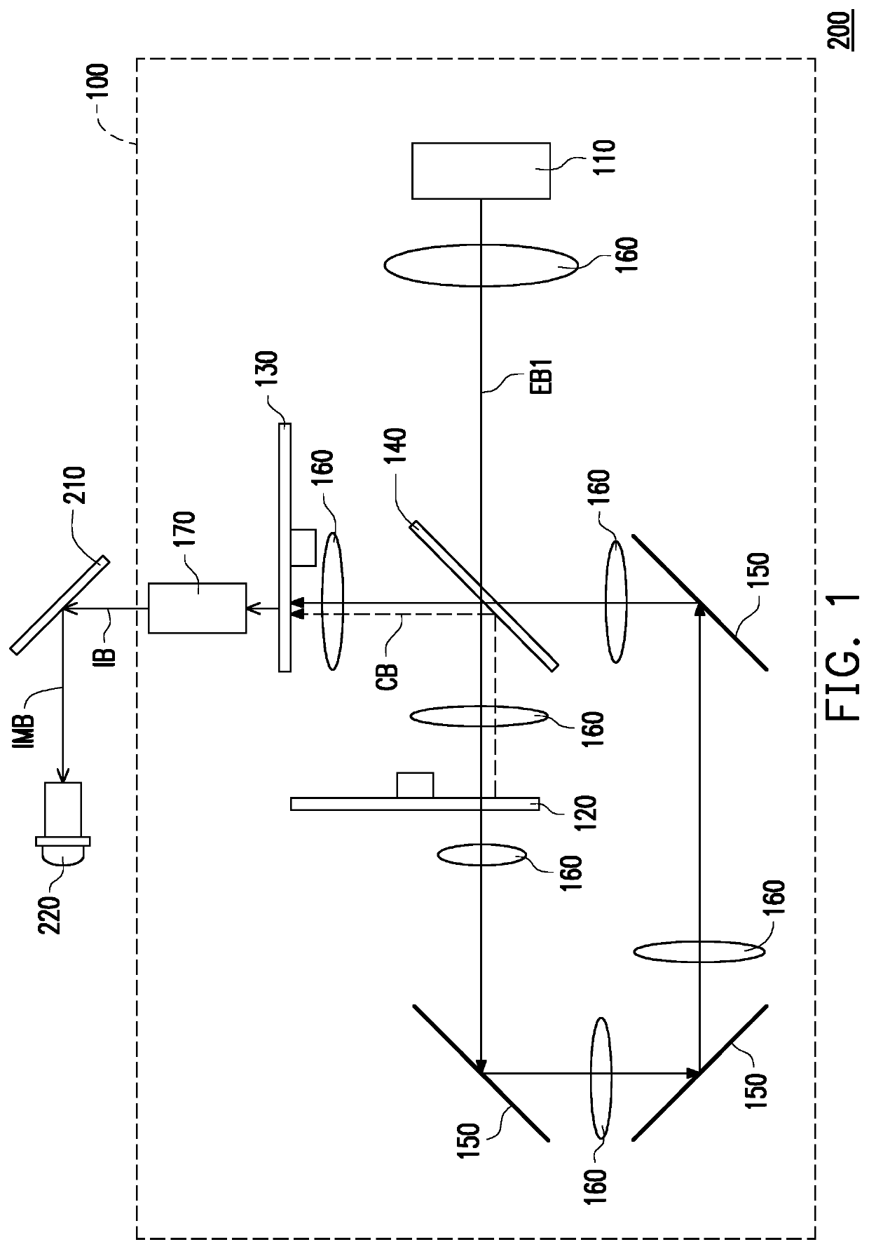
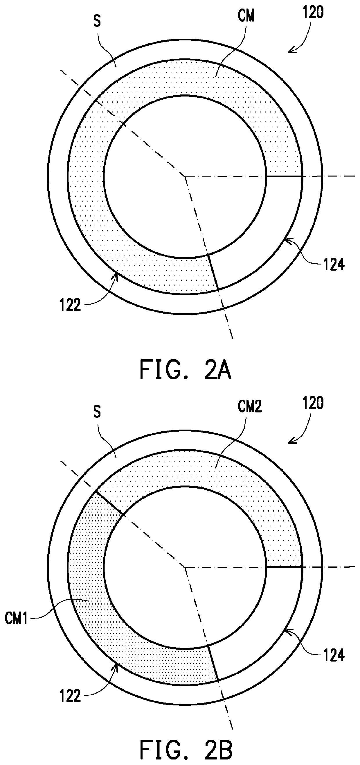
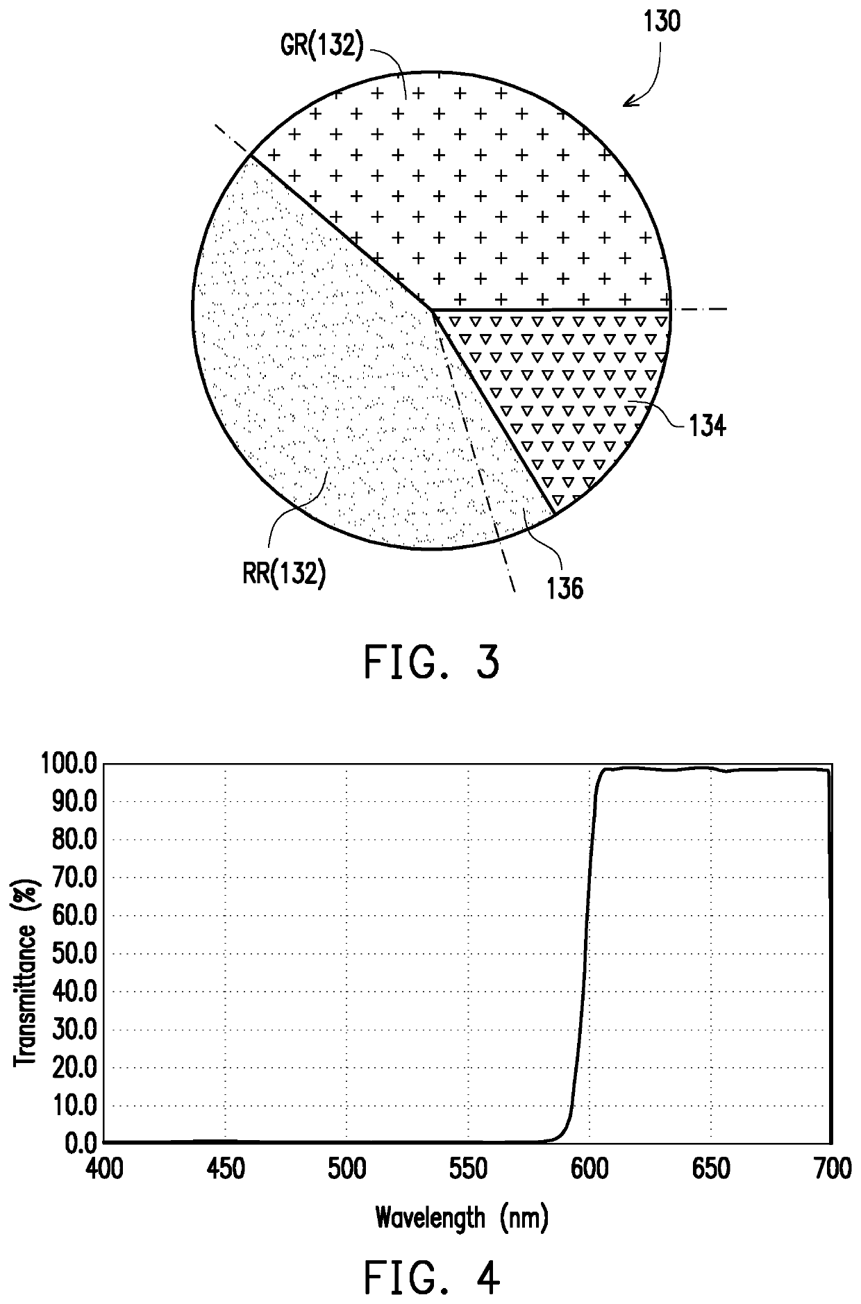
[0035]FIG. 1 is a schematic view illustrating a projection apparatus according to the invention. FIG. 2A is a schematic front view illustrating a wavelength conversion wheel of FIG. 1. FIG. 3 is a schematic front view illustrating an example of a filter wheel of FIG. 1. FIG. 4 is a diagram showing a transmittance spectrum of a red light filter region in FIG. 3. For the clarity of illustration, FIGS. 2A and 3, and subsequent related figures specifically show dashed lines to more easily indicate the angles of various regions of the wavelength conversion wheel and the filter wheel.

[0036]Referring to FIG. 1, a projection apparatus 200 of this embodiment includes an illumination system 100, a light valve 210, and a projection lens 220. The illumination system 100 is configured to emit an illumination beam D3. The light valve 210 is disposed on the transmission path of the illumination beam D3 to modulate the illumination beam D3 to an image beam IMB. The projection lens 220 is disposed o...

second embodiment

[0059]FIG. 7 is a schematic view illustrating a projection apparatus according to the invention. FIG. 8 is a schematic front view illustrating a wavelength conversion wheel of FIG. 7. In the embodiment shown in FIG. 7 to FIG. 8, the configurations and functions of a first excitation light source 310, a filter wheel 330, lenses 360, a light uniforming element 370, a light valve 410, and a projection lens 420 are similar to the configurations and functions of the first excitation light source 110, the filter wheel 130, the lenses 160, the light uniforming element 170, the light valve 210, and the projection lens 220. Therefore, details thereof will not be repeated in the following. Referring to FIG. 7 and FIG. 8, the main difference between a projection apparatus 400 of this embodiment and the projection apparatus 200 of FIG. 1 is that the wavelength conversion wheel 120 of the projection apparatus 200 is a transmissive wavelength conversion wheel, while a wavelength conversion wheel ...

third embodiment

[0062]FIG. 9A is a schematic view illustrating a light path of a projection apparatus within a first time interval according to the invention. FIG. 9B is a schematic view illustrating a light path of the projection apparatus of FIG. 9A within a second time interval. FIG. 10 is a schematic front view illustrating a wavelength conversion wheel of FIGS. 9A and 9B. FIG. 11 is a schematic front view illustrating an example of a filter wheel in FIGS. 9A and 9B. FIG. 12 is a diagram showing a transmittance spectrum of a second region in FIG. 11. In the embodiment shown in FIG. 9A to FIG. 11, the configurations and functions of a first excitation light source 510, a light splitting and combining module 540, reflecting mirrors 550, lenses 560, a light uniforming element 570, a light valve 610, and a projection lens 620 are similar to the configurations and functions of the first excitation light source 110, the light splitting and combining module 140, the reflecting mirrors 150, the lenses ...


PUM


Abstract

An illumination system including a first excitation light source, a wavelength conversion wheel, and a filter wheel is provided. The first excitation light source is configured to emit a first excitation beam. The wavelength conversion wheel includes a wavelength conversion region and a first optical region. The wavelength conversion region and the first optical region alternately enter a transmission path of the first excitation beam. The first excitation beam is converted into a conversion beam by the wavelength conversion region when the wavelength conversion region enters the transmission path of the first excitation beam. The filter wheel includes a first region, a second region, and a blocking region. An angle covered by the second region in a circumferential direction is smaller than an angle covered by the first optical region. A projection apparatus is also provided.

Description

CROSS-REFERENCE TO RELATED APPLICATION[0001]This application claims the priority benefit of China application serial no. 201811009876.7, filed on Aug. 31, 2018. The entirety of the above-mentioned patent applications is hereby incorporated by reference herein and made a part of this specification.BACKGROUND OF THE INVENTION1. Field of the Invention[0002]The invention relates to an optical system and an optical apparatus, and particularly relates to an illumination system and a projection apparatus adopting the illumination system.2. Description of Related Art[0003]The imaging principle of a projection apparatus is to convert an illumination beam generated by an illumination system into an image beam through a light valve, and then project the image beam to a screen through a projection lens, so as to form an image. The illumination system of the projection apparatus includes a wavelength conversion wheel and a filter wheel. A plurality of optical regions of the wavelength conversion...

Claims


Application Information

Patent Timeline
Patent Type & Authority Applications(United States)
IPC IPC(8): G03B21/20G03B33/08
CPCG03B21/2033F21V9/40G03B21/2066G03B33/08G03B21/204G02B26/008G02B26/00G03B21/20
Inventor CHEN, SHUN-TAILIN, SHU-YUWENG, MING-TSUNGHONG, CHEN-YIFAN, CHEN-WEI
Owner CORETRONIC
Why Eureka
Try Eureka