Magnetic resonance imaging apparatus, image processor, and image processing method

Pending Publication Date: 2020-03-12
FUJIFILM HEALTHCARE CORP
View PDF1 Cites 6 Cited by
  • Summary
  • Abstract
  • Description
  • Claims
  • Application Information

AI Technical Summary

Benefits of technology

[0012]According to the invention, by integrating a specific tissue extraction mask image which is created by extracting a specific tissue in a target part and a blood vessel extraction mask image which is created separately from the specific tissue extraction mask image on the basis of a landmark included in the target part, creating an MRA mask (an integrated mask image), and using this mask image for clipping blood vessels from a three-dimensional image, it is possible to extract

Problems solved by technology

In the related art, clipping is manually performed and is a troublesome operation requiring labor, but automation techniques have also been proposed.
However, since the thickness of a blood vessel differs depending on examinees, there is a likelihood that a thick blood vessel will not be appropriately identified and an unnecessary blood vessel will be extracted.
When there is ste

Method used


Image

  • Magnetic resonance imaging apparatus, image processor, and image processing method
  • Magnetic resonance imaging apparatus, image processor, and image processing method
  • Magnetic resonance imaging apparatus, image processor, and image processing method

Examples


first embodiment

[0032]First, the outline of an MRI apparatus according to a first embodiment will be described with reference to FIGS. 1 and 2.

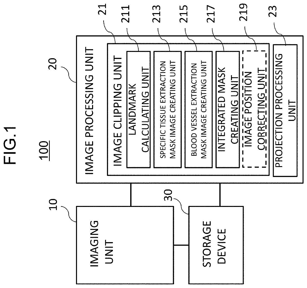
[0033]As illustrated in FIG. 1, an MRI apparatus 100 includes an imaging unit 10 that generates nuclear magnetic resonance in nuclei of atoms constituting tissues of an examinee placed in a static magnetic field, collects nuclear magnetic resonance signals generated in response thereto, and acquires an examinee image (an MR image), an image processing unit 20 that performs various operations on the MR image acquired by the imaging unit 10, and a storage device 30 that stores process results and the like of the imaging unit 10 and the image processing unit 20.

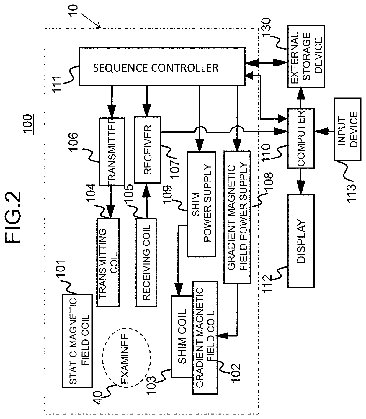
[0034]The imaging unit 10 is the same as a general MRI apparatus and includes a static magnetic field coil 101 of super-conduction, normal-conduction, or the like or a permanent magnet that generates a static magnetic field in a space (an imaging space) in which an examinee 40 is placed, a gradient magne...

modified example 1

of Brain Extraction Mask Image Calculation

[0084]In the first embodiment, an SNR image which is an image indicating homogeneity is created with attention on homogeneity of signal intensity of cerebral parenchyma, and processing such as binarization and extension is performed on the basis thereof, and a brain extraction mask image is calculated (FIG. 5: S32). In this modified example, the homogeneity of signal intensity of cerebral parenchyma is used similarly to the first embodiment, but a brain tissue is extracted using the area extension method in this modified example.

[0085]The processes in this modified example will be described below with reference back to the flow illustrated in FIG. 8 which has been referred to in the first embodiment. The process flow of the modified example in FIG. 8 is indicated by a dotted arrow.

[0086]First, a seed point is set in a three-dimensional image (S320-1). A seed point may be set to, for example, a point located a predetermined distance (a distan...

modified example 2

of Brain Extraction Mask Image Calculation

[0090]In the first embodiment and the modified example (Modified Example 1 of brain extraction mask image calculation), a brain tissue is extracted from a three-dimensional image using homogeneity of signal intensity of cerebral parenchyma. On the other hand, in this modified example, a brain is extracted by removing signals of tissues other than a brain tissue, for example, subcutaneous fat or bonemarrow of the skull, from the three-dimensional image.

[0091]The processes in this modified example will be described below with reference to the flow illustrated in FIG. 17.

[0092]First, a three-dimensional image is binarized using a threshold value and a binary image in which a value equal to or greater than the threshold value is set to 1 and a value less than the threshold value is set to 0 is calculated (S32-1). In an MRA image, signal values decrease in the order of a blood vessel (a bloodstream), subcutaneous fat, cerebral parenchyma, a skull...


PUM


Abstract

An automatic clipping technique capable of satisfactorily extracting blood vessels to be extracted is provided. A specific tissue extraction mask image which is created by extracting a specific tissue (for example, a brain) from a three-dimensional image acquired by magnetic resonance angiography and a blood vessel extraction mask image which is created by extracting a blood vessel from an area (a blood vessel search area) which is determined using a preset landmark position and the specific tissue extraction mask image are integrated to create an integrated mask. By applying the integrated mask to the three-dimensional image, a blood vessel is clipped from the three-dimensional image.

Description

BACKGROUND OF THE INVENTIONField of the Invention[0001]The present invention relates to a technique of processing a blood vessel image which is acquired by a medical imaging apparatus such as a magnetic resonance imaging apparatus (hereinafter referred to as an MRI apparatus) and particularly to a technique of clipping only a blood vessel from a three-dimensional image.Description of the Related Art[0002]A blood vessel image is used to diagnose angiostenosis of a brain or the like. A blood vessel image can be acquired, for example, by two-dimensionally projecting a three-dimensional image including blood vessels, which is acquired using magnetic resonance angiography (MRA), using a maximum intensity projection (MIP) method. By changing the projecting directions, a blood vessel image can be seen from all angles and blood vessel abnormality or the like hidden in a thick blood vessel or the like can also be found out. Since a blood vessel image acquired by projection also includes unne...

Claims


Application Information

Patent Timeline
IPC IPC(8): A61B5/00G06T7/00G06T15/30G06K9/46G06T3/00A61B5/055A61B5/02G01R33/563G01R33/56G06V10/25
CPCG01R33/5635A61B5/0042G06T2207/20182G06T2207/30016G06T15/30A61B5/02007G01R33/5608G06T3/0068G06T2207/30104G06T2207/20081G06K9/46A61B5/055G06T7/0012G06T2207/10088G06T7/11G06T2207/30101G06V20/64G06V10/25G06V2201/031
Inventor SHIRAI, TORUYOKOSAWA, SUGURUNAGAO, HISAKOYOSHIDA, YASUHIDEKAWATA, YASUOHARADA, KUNIAKI
Owner FUJIFILM HEALTHCARE CORP
Why Eureka
Try Eureka