
Wrist orthosis

a wrist and wrist technology, applied in the field of orthopaedic orthosis, can solve the problems of insufficient absorbed local pressure points, tissue diffused pressure, and discomfort of patients, and achieve the effects of minimizing bacterial growth, avoiding pressure, and facilitating the movement of both the index and middle finger

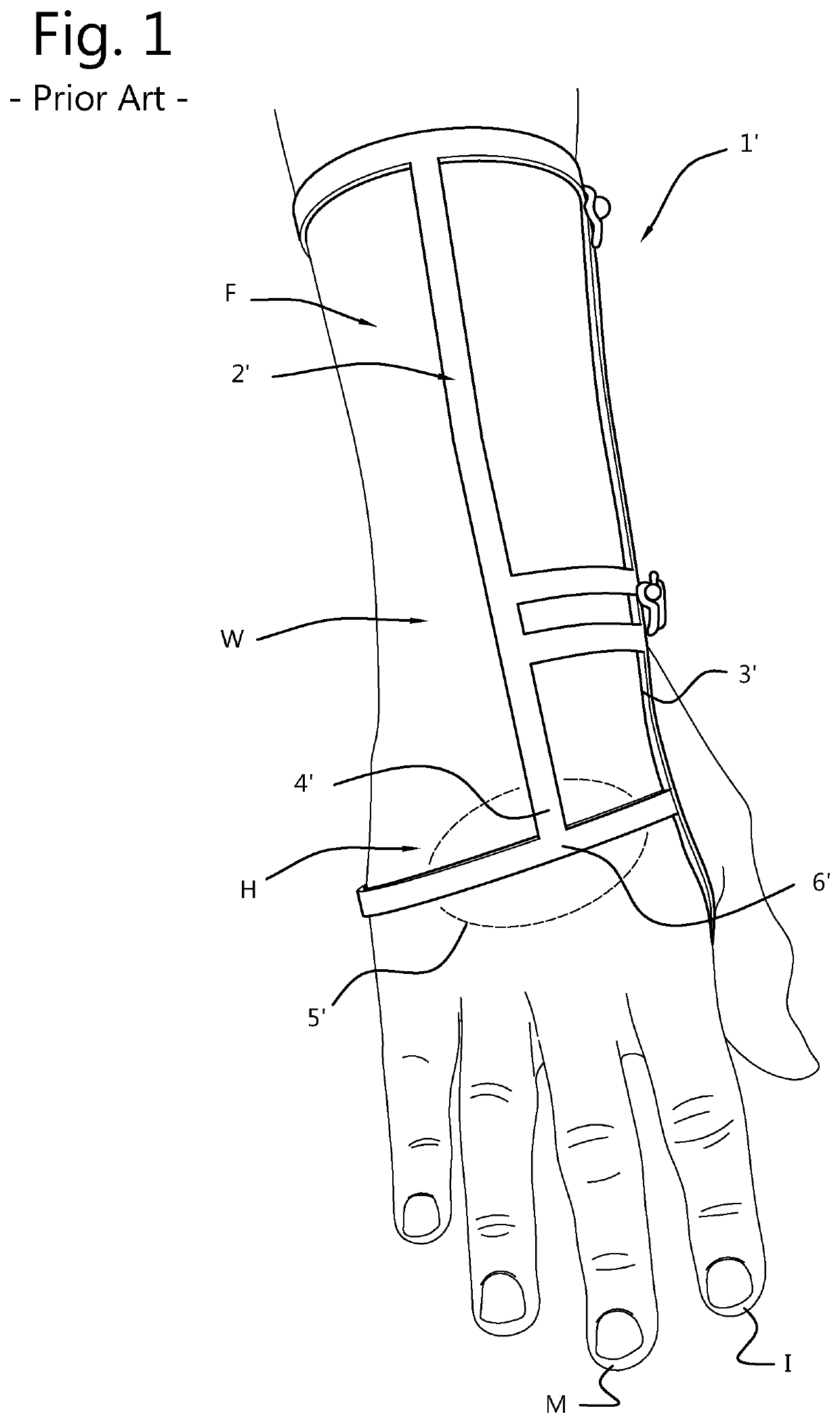
Inactive Publication Date: 2020-03-12
WE DESIGN BEHEER BV
View PDF0 Cites 2 Cited by
  • Summary
  • Abstract
  • Description
  • Claims
  • Application Information

AI Technical Summary

Benefits of technology

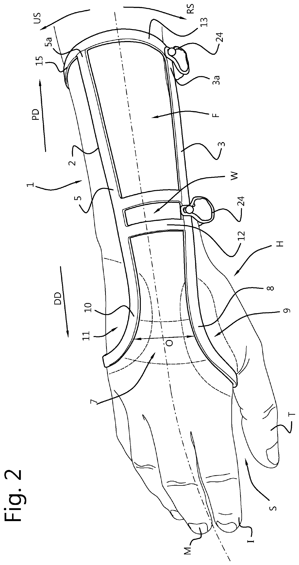
The present invention provides a wrist orthosis that allows more freedom of movement of the fingers by avoiding pressure on the dorsal side of the hand. It also allows for adjustment to fit different sizes of the hand by bending the wrist orthosis. The wire frame is made of a metal or metal alloy, which can be bent for achieving a desired shape or made with small or minor adjustments. The material used for the wire frame is biologically inert, minimizing bacterial growth on and around the wrist orthosis.

Problems solved by technology

However, even though such a frame-based wrist orthosis may provide the required support from an orthopaedic point of view, the frame may sometimes cause discomfort to a patient.
For example, in particular cases a frame-based wrist orthosis may cause discomfort at places where the skin and underlying tissue on bone structure is relatively thin, causing localized pressure points that may not be sufficiently absorbed and diffused by tissue, especially when the thumb and index fingers are pressed together for gripping, thereby tensioning the tendons on the dorsal side of the hand.

Method used


Image

  • Wrist orthosis
  • Wrist orthosis
  • Wrist orthosis

Examples


embodiment 1

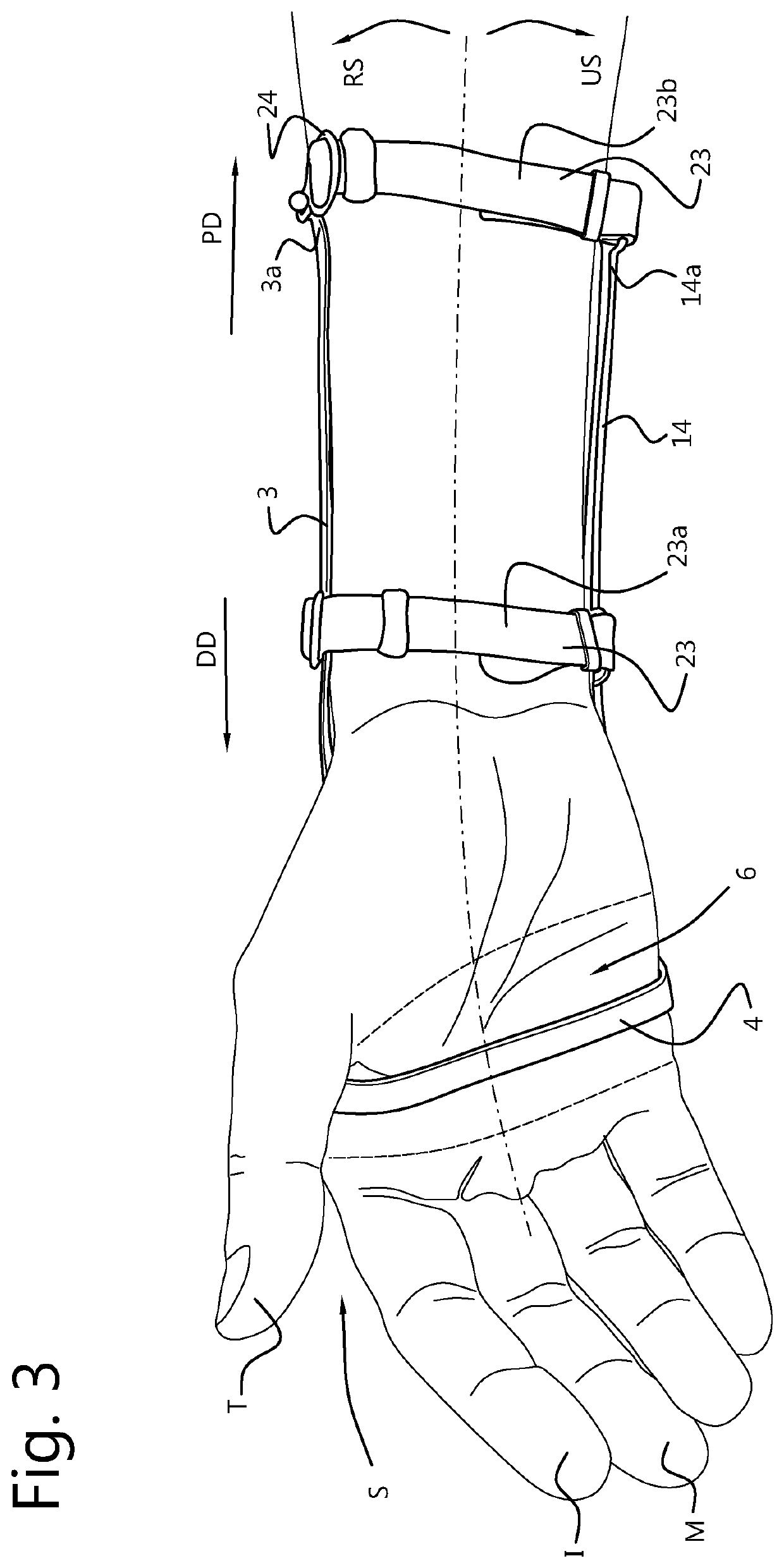
[0054]A wrist orthosis (1) for support of a patient's wrist, comprising a wire frame (2) which is configured to a engage a forearm (F), wrist (W), and hand (H) of a patient, wherein the wire frame (2) comprises a continuous connection of

[0055]a radial wire section (3) configured to extend in a distal direction along the forearm, wrist and a radial side of the hand to an interdigital space (S) between the thumb and index finger of the hand, wherein the radial wire section (3) is connected to

[0056]a palmar wire section (4) configured to extend in a lateral direction from the interdigital space (S) along a palmar region (6) of the hand toward an ulnar side of the hand, and wherein the palmar wire section (4) is connected to an

[0057]ulnar wire section (5) configured to extend from the ulnar side of the hand in proximal direction toward and along the wrist and forearm; and wherein

[0058]the radial wire section (3) and the ulnar wire section (5) are laterally spaced apart along an intermed...

embodiment 2

[0059]The wrist orthosis (1) according to embodiment 1, wherein the radial wire section (3) comprises an inward bend (8) configured to extend along a first dorsal interosseous region (9) of the hand and wherein the ulnar wire section (5) comprises an inward bend (10) configured to extend along a dorsal ulnar region (11) of the hand.

embodiment 3

[0060]The wrist orthosis (1) according to embodiment 1 or 2, wherein the radial wire section (3), the palmar wire section (4), and the ulnar wire section (5) are formed as a continuous single piece of bent wire.


PUM


Abstract

A wrist orthosis (1) for support of a patient's wrist, comprising a wire frame (2) for engagement with a forearm (F), wrist (W), and hand (H) of a patient, the wire frame (2) comprising a radial wire section (3) configured to extend in a distal direction along the forearm, wrist and toward a radial side of the hand. The radial wire section (3) is connected to a palmar wire section (4) configured to extend in lateral direction from the radial side of the hand along a palmar region (6) thereof toward an ulnar side of the hand. The palmar wire section (4) is connected to an ulnar wire section (5) configured to extend from the ulnar side of the hand in proximal direction toward an along the wrist and forearm. The radial and ulnar wire sections (3,5) are laterally spaced apart along an intermediate dorsal region (7) of the hand.

Description

FIELD OF THE INVENTION[0001]The present invention relates to an orthopaedic orthosis, in particular a frame / wire-based wrist orthosis for immobilizing the wrist of a patient.BACKGROUND ART[0002]There are known wrist orthoses made of a frame / wire which is shaped to snugly fit around a patient's wrist for support thereof. An advantage of such a frame / wire-based wrist orthosis is that it is waterproof and that it provides a low profile and sleek design, allowing the wrist orthosis to not interfere as much with clothing around a patient's arm compared to other known wrist orthoses.[0003]However, even though such a frame-based wrist orthosis may provide the required support from an orthopaedic point of view, the frame may sometimes cause discomfort to a patient. For example, in particular cases a frame-based wrist orthosis may cause discomfort at places where the skin and underlying tissue on bone structure is relatively thin, causing localized pressure points that may not be sufficientl...

Claims


Application Information

Patent Timeline
Patent Type & Authority Applications(United States)
IPC IPC(8): A61F5/01A61F5/30A61F13/10
CPCA61F2005/0165A61F5/0118A61F5/30A61F2005/0146A61F13/108A61F5/05A61F5/05866A61F5/24
Inventor ENGELSHOVEN, WOUTER ROBIN
Owner WE DESIGN BEHEER BV
Learn More