System and method for generating an orthodontic appliance

a technology of orthodontic appliances and systems, applied in the field of systems, can solve the problems of high patient cost, inability to pre-model, and insufficient patient comfort,

Inactive Publication Date: 2020-03-12
DSD APPLICANT LLC
View PDF0 Cites 16 Cited by
  • Summary
  • Abstract
  • Description
  • Claims
  • Application Information

AI Technical Summary

Benefits of technology

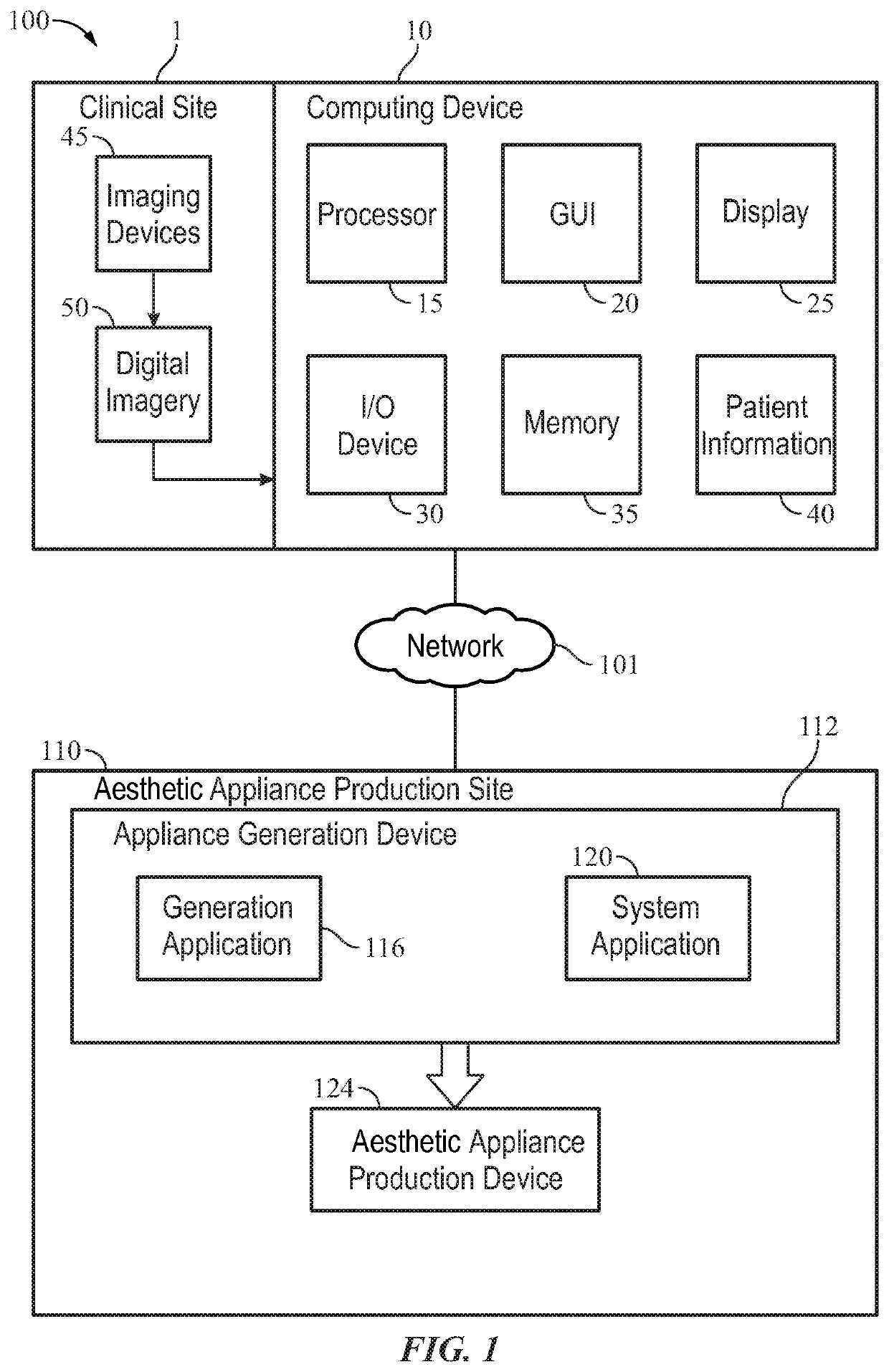
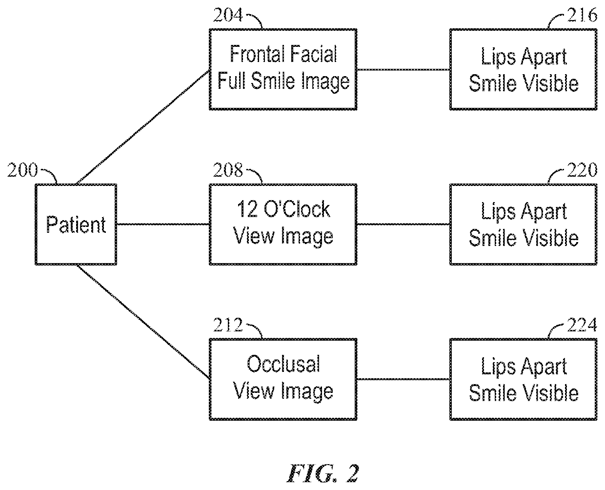
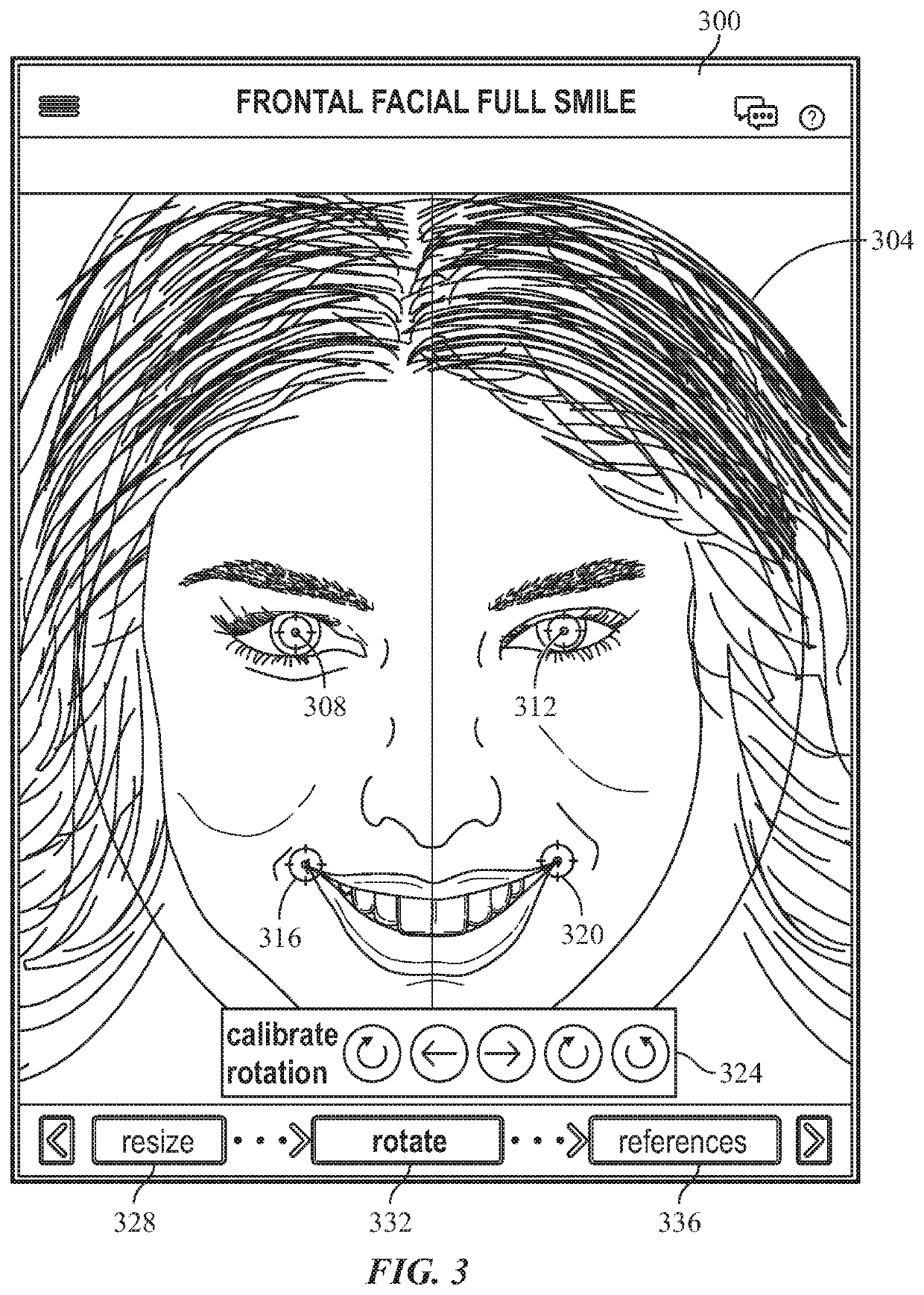
The patent describes a system and method for creating digital dentition simulations and producing aesthetic appliances. The system includes a clinical site with imaging devices to capture digital images of the patient, which are transmitted to a computing device for calibration and selection of a template with desired tooth configurations. The computing device generates a dentition simulation which is sent to an aesthetic appliance production site for creating the final dentition and rendering a smile. The claimed patent provides an efficient way to create customized aesthetic appliances by integrating dental imaging, computing, and 3D printing technologies.

Problems solved by technology

Such an approach requires a significant amount of time, labor, and accuracy resulting in high costs to the patient.
These system do not provide the opportunity to pre-model the new smile of the patient using a variety of 3-dimensional views which can be used to help convert the potential client to buy the final developed aesthetic appliance.

Method used


Image

  • System and method for generating an orthodontic appliance
  • System and method for generating an orthodontic appliance
  • System and method for generating an orthodontic appliance

Examples


Embodiment Construction

[0028]The specific details of the single embodiment or variety of embodiments described herein are to the described system and methods of use. Any specific details of the embodiments are used for demonstration purposes only and not unnecessary limitations or inferences are to be understood therefrom.

[0029]Any reference to “invention” within this document is a reference to an embodiment of a family of inventions, with no single embodiment including features that are necessarily included in all embodiments, unless otherwise stated. Furthermore, although there may be references to “advantage's” provided by some embodiments, other embodiments may not include those same advantages or may include different advantages. Any advantages described herein are not to be construed as limiting to any of the claims.

[0030]Before describing in detail exemplary embodiments, it is noted that the embodiments reside primarily in combinations of components related to the system and method. Accordingly, th...


PUM

PropertyMeasurementUnit
Angleaaaaaaaaaa

Abstract

The present embodiments, discloses a system and method for generating an aesthetic appliance including a clinical site having a plurality of imaging devices to capture digital imagery of a patient. A computing device receives the digital imagery and transmits the imagery, via a network, to an aesthetic appliance production site. The aesthetic appliance production site includes an aesthetic appliance production device configured to produce the aesthetic appliance.

Description

TECHNICAL FIELD[0001]The embodiments presented provide a system and method for generating an aesthetic appliance using a computer program.BACKGROUND[0002]One of the most critical steps to increase case acceptance for aesthetic treatment of a smile is to present the patient with a rendering of their new smile. Today's orthodontists often take plaster models of the upper and lower jaw and cut the model into single tooth models which are aligned and positioned within the wax bed. A wire can then be bound to a bracket positioned on each tooth. This informs the orthodontist of the necessary geometry of the wire to achieve the desired aesthetic result. Small templates for every tooth would then be made to ensure the brackets will be bonded at a proper location on the teeth of the patient. Such an approach requires a significant amount of time, labor, and accuracy resulting in high costs to the patient.[0003]More recently, computer-driven approaches have been utilized to visualize the untr...

Claims


Application Information

Patent Timeline
IPC IPC(8): G05B19/4099G06F17/50A61C7/00A61C9/00
CPCG06T2219/2016G06T2210/41A61C7/002G05B2219/49023G06T2200/24G06F30/20G06T3/0075A61C9/0046G06T19/20G05B19/4099G06T2219/2004G06T3/60A61C9/0053A61C13/0004A61C13/0019A61C13/082G06T3/147
Inventor GEORG, RALPHCOACHMAN, CHRISTIAN
Owner DSD APPLICANT LLC
Why Eureka
Try Eureka