
Pneumatic scissor tool

a pneumatic scissor and tool technology, applied in the field of power scissor tools, can solve the problems of insufficient structural strength and cam damage, and achieve the effects of thicker thickness, higher hardness, and increased reaction for

Inactive Publication Date: 2020-03-19
DIN LONG IND
View PDF0 Cites 1 Cited by
  • Summary
  • Abstract
  • Description
  • Claims
  • Application Information

AI Technical Summary

Benefits of technology

The invention is a pneumatic scissor tool that has a housing with a mounting opening and a driving wheel. The tool has a unique design with multiple supporting columns that are tightly connected, allowing for a larger reaction force to be directed to the blade during use. This results in a more powerful cutting tool that can handle materials with higher hardness or thickness.

Problems solved by technology

Thus, the cam may be damaged due to insufficient structural strength as the hardness of the material to be sheared is too high.

Method used


Image

  • Pneumatic scissor tool
  • Pneumatic scissor tool
  • Pneumatic scissor tool

Examples


Embodiment Construction

[0021]The detailed description and technical contents of the present invention will now be described with reference to the drawings as follows:

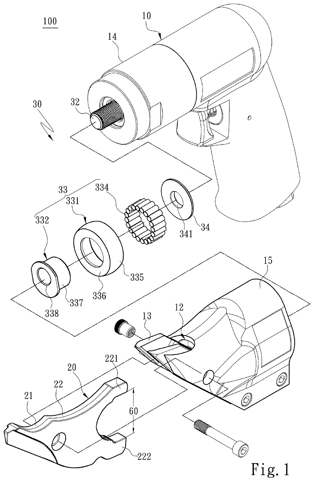
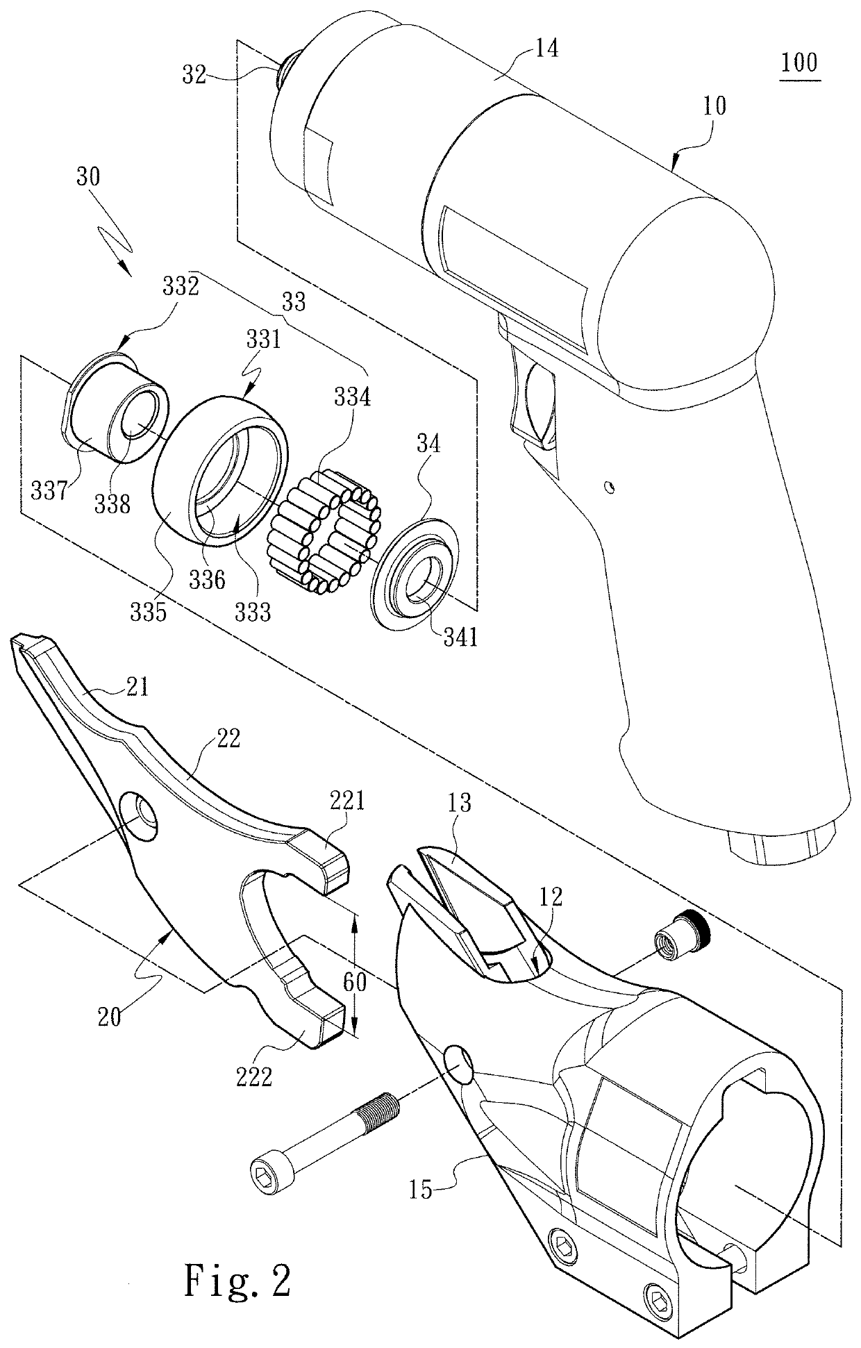
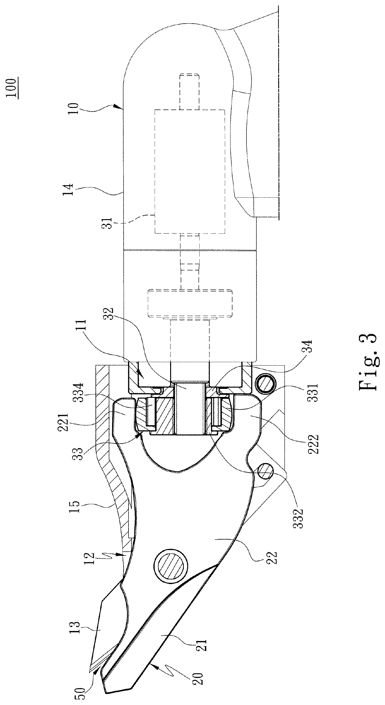
[0022]Referring to FIG. 1, FIG. 2, and FIG. 3, the present invention provides a pneumatic scissor tool 100 that is able to shear a material (e.g., an iron plate, etc.). The pneumatic scissor tool 100 includes a tool housing 10, a movable blade 20, and a power assembly 30. The tool housing 10 includes an appearance that is designed according to the user's needs or habits. The tool housing 10 is formed with an assembly space 11 and a mounting opening 12, wherein the mounting opening 12 is located at one end of the whole structure of the tool housing 10 and communicates with the assembly space 11. In addition, the tool housing 10 is provided with a fixed blade 13 at the position of the mounting opening 12. On the other hand, for the purpose that the movable blade 20 is fitted with the fixed blade 13, the movable blade 20 is provided at the mount...


PUM

PropertyMeasurementUnit
thicknessaaaaaaaaaa
thicknessaaaaaaaaaa
diameteraaaaaaaaaa

Abstract

A pneumatic scissor tool comprises a tool housing, a movable blade and a power assembly, the tool housing comprises an assembly space, a mounting opening and a fixed blade, wherein the fixed blade is arranged at the mounting opening, the movable blade is arranged at the mounting opening corresponding to the fixed blade. Further, the power assembly comprises a pneumatic motor, a transmission shaft and an eccentric driving wheel. The eccentric driving wheel is connected with the transmission shaft and comprises an outer ring member, a bearing block, a column mounting space and a plurality of supporting columns, the outer ring member is used for pushing the movable blade, the bearing block is arranged in the outer ring member and installed in an eccentric manner with the transmission shaft, and the supporting columns is arranged in the column mounting space and are tightly connected with each other.

Description

FIELD OF THE INVENTION[0001]The invention relates to a power scissor tool, in particular to a pneumatic scissor tool which comprises an eccentric driving wheel and is used for bearing larger reaction force.BACKGROUND OF THE INVENTION[0002]As the industrial technology advances, conventional scissors, which apply force by holding the handle of the scissor by hands, and the blade of which is pushed according to the lever principle to cut hard materials, are not favored by consumers anymore, but the power scissors driven by pneumatic or electric power and the like are used instead. Further, nowadays, the shearing target is no longer just an article with no obvious rigidity such as paper or branches, but the implementation of shearing metal plates is appeared.[0003]A related conventional power scissor is seen in TW M297827, which provides a power scissor structure including essentially a hollow grip, a front cover holder connected to the hollow grip, and a shear blade connected to the fr...

Claims


Application Information

Patent Timeline
Patent Type & Authority Applications(United States)
IPC IPC(8): B26B15/00
CPCB23D29/005B26B15/00
Inventor HSIEH, JUNG-FU
Owner DIN LONG IND
Learn More