Coil component
- Summary
- Abstract
- Description
- Claims
- Application Information
AI Technical Summary
Benefits of technology
Problems solved by technology
Method used
Image
Examples
first embodiment
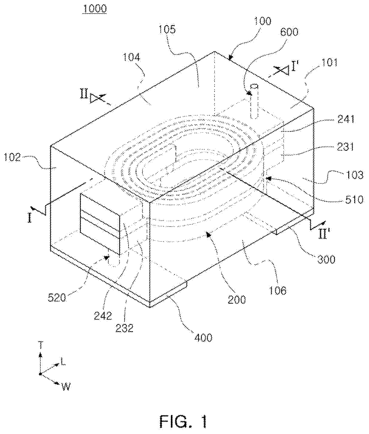
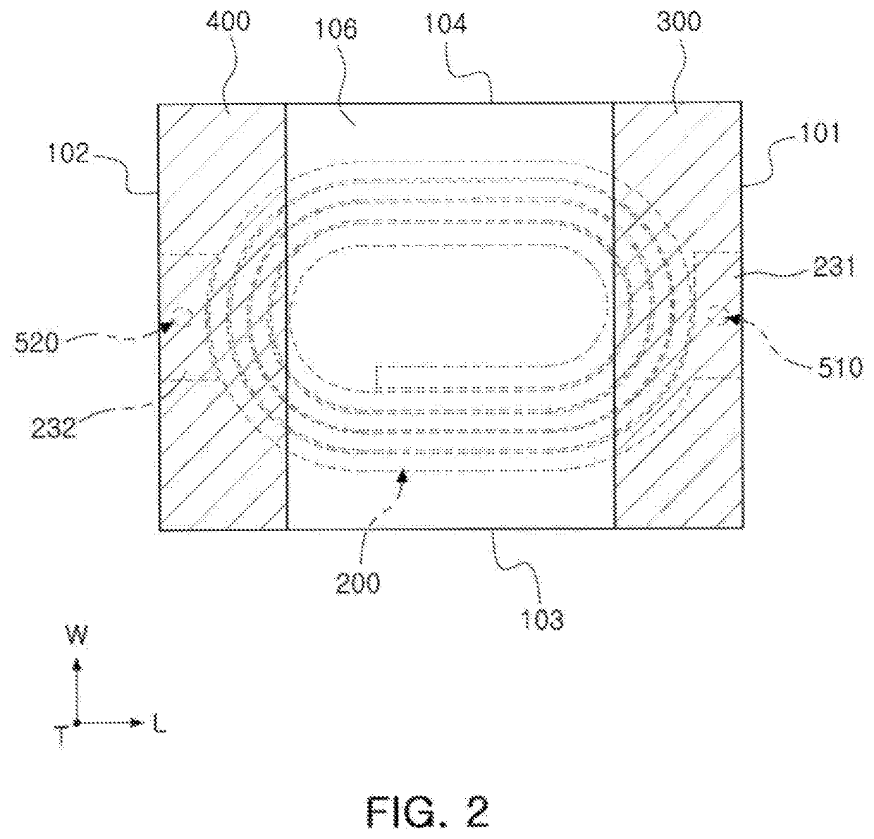
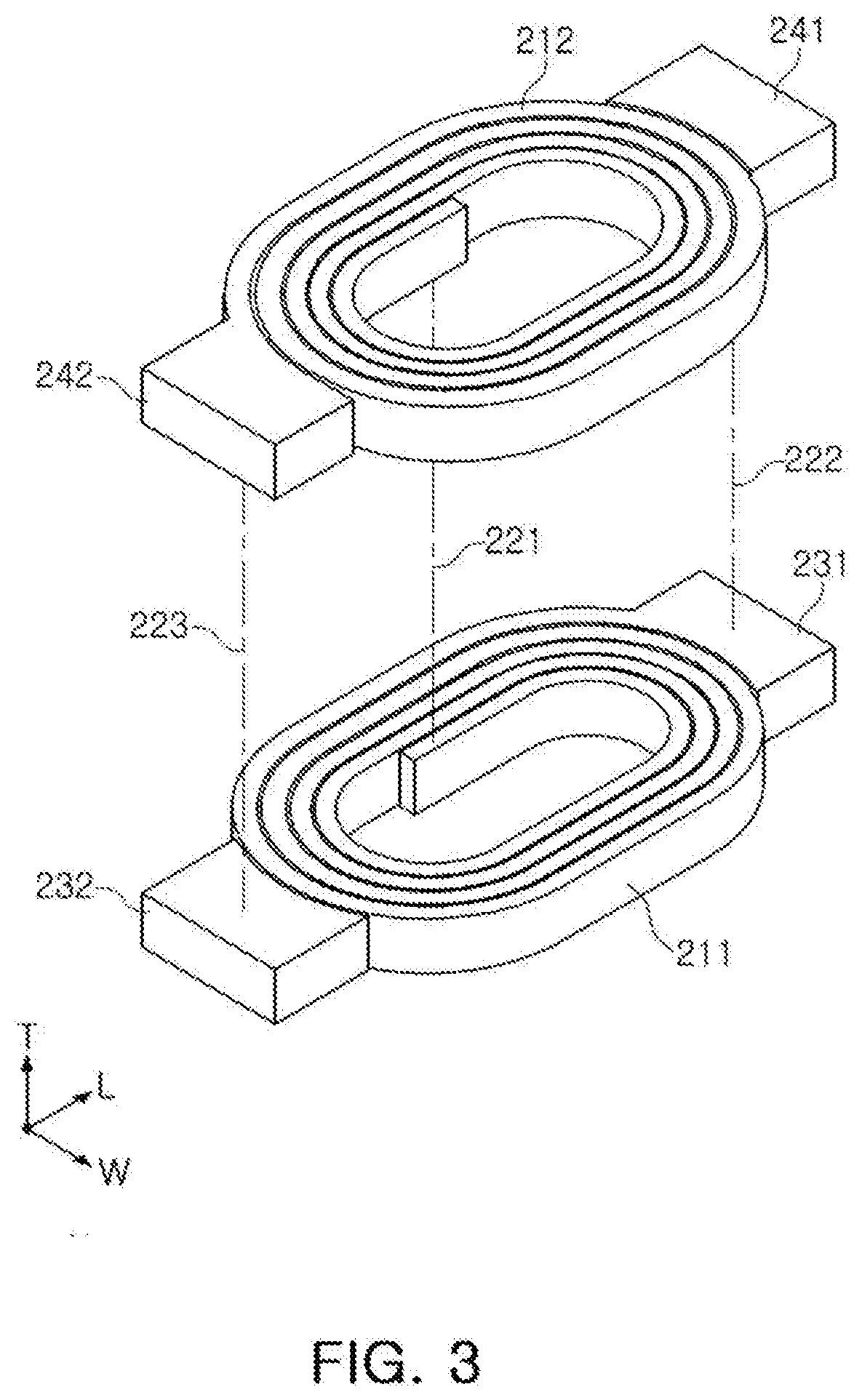
[0028]FIG. 1 is a schematic diagram of a coil component according to a first embodiment in the present disclosure. FIG. 2 is a diagram showing the coil component when viewed from a lower side of FIG. 1. FIG. 3 is an exploded view of a coil portion. FIG. 4 is a cross-sectional view taken along line I-I′ of FIG. 1, and FIG. 5 is a cross-sectional view taken along line II-II′ of FIG. 1.
[0029]Referring to FIGS. 1 to 5, a coil component 1000 according to the first embodiment may include a body 100, an internal insulating layer IL, a coil portion 200, external electrodes 300 and 400, connection electrodes 510 and 520, and a support electrode 600.
[0030]The body 100 forms an exterior of the coil component 1000, and the coil portion 400 is embedded in the body 100.
[0031]The body 100 may have a substantially hexahedral shape.
[0032]The body 100 may have, on the basis of FIG. 1, a first surface 101 and a second surface 102 opposing each other in a length direction L, a third surface 103 and a f...
second embodiment
[0072]FIG. 6 is a schematic diagram of a coil component according to a second embodiment in the present disclosure, and FIG. 7 is a cross-sectional view taken along line III-III′ of FIG. 6.
[0073]Referring to FIGS. 1 to 7, a coil component 2000 according to this embodiment has support electrodes 610 and 620 different from the support electrode 600 of the coil component 1000 according to the first embodiment. Therefore, this embodiment will be described with respect to only the support electrodes 610 and 620, which are a difference from the first embodiment. The descriptions of other elements of the first embodiment may be applied, as it is, to the other elements of this second embodiment.
[0074]The supporting electrodes 610 and 620, applied to this embodiment, are formed as a pair of support electrodes, and the pair of support electrodes 610 and 620 are respectively formed on the first and second auxiliary lead-out patterns 241 and 242 to be spaced apart from each other. Each of the p...
third embodiment
[0076]FIG. 8 is a schematic diagram of a coil component according to a third embodiment in the present disclosure, and FIG. 9 is a cross-sectional view taken along line IV-IV′ of FIG. 6.
[0077]Referring to FIGS. 1 to 8, a coil component 3000 according to this embodiment has a coil portion 200 different from that of the coil components 1000 and 2000 according to the first and second embodiments. Therefore, this embodiment will only be described with respect to the coil portion 200, which is a difference from the first and second embodiment. The descriptions of other elements of the first and second embodiments may be applied, as it is, to the other elements of this third embodiment.
[0078]The coil portion 200, applied to this embodiment, extends from each of lead-out patterns 231 and 232 and auxiliary lead-out patterns 241 and 232 to further include bonding enhancing portions 251, 252, 253, and 254 exposed to first and second surfaces 101 and 102. Specifically, the coil portion 200 inc...
PUM
 Abstract
Description
Claims
Application Information
 - R&D
- Intellectual Property
- Life Sciences
- Materials
- Tech Scout
- Unparalleled Data Quality
- Higher Quality Content
- 60% Fewer Hallucinations
Browse by: Latest US Patents, China's latest patents, Technical Efficacy Thesaurus, Application Domain, Technology Topic, Popular Technical Reports.
© 2025 PatSnap. All rights reserved.Legal|Privacy policy|Modern Slavery Act Transparency Statement|Sitemap|About US| Contact US: help@patsnap.com


