Welded combination visual sensor device

A visual sensor and sensor technology, applied in welding equipment, welding/welding/cutting items, arc welding equipment, etc., can solve the problems of no sensor device protection, inability to realize groove measurement, and inability to realize medium and thick plate workpieces at the same time, etc. , to achieve the effect of reducing position error, position and angle ease

Active Publication Date: 2015-12-23
XIAMEN UNIV OF TECH
View PDF12 Cites 7 Cited by
  • Summary
  • Abstract
  • Description
  • Claims
  • Application Information

AI Technical Summary

Problems solved by technology

The patented laser ranging sensor is to assist the CCD camera in visual positioning, and cannot achieve groove measurement
[0007] To sum up, none of the existing technologies can realize the two functions of groove measurement and weld pool observation of medium and heavy plate workpieces at the same time, and none of them protects the sensing device.

Method used


Image

  • Welded combination visual sensor device
  • Welded combination visual sensor device
  • Welded combination visual sensor device

Examples


Embodiment Construction

[0034] The present invention will be further described in detail below in conjunction with the accompanying drawings and specific embodiments.

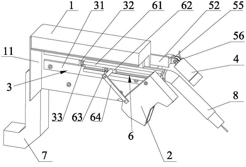
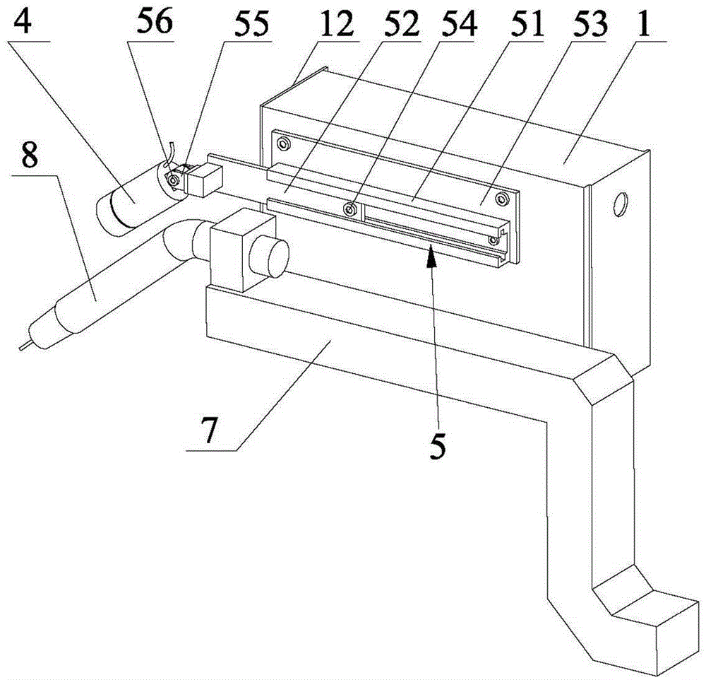
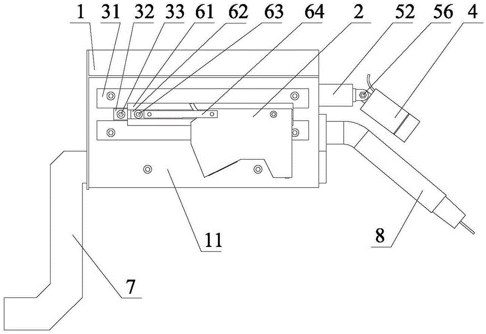
[0035] Disclosed in the present invention is a welded combined vision sensor device, such as Figure 1 to Figure 5 Shown is a preferred embodiment of the present invention. The combined vision sensor device includes a base 1 , a line laser sensor 2 , a line laser slide-out mechanism 3 , a CCD camera module 4 and a CCD slide-out mechanism 5 , and may further include a line laser angle adjustment mechanism 6 . in:

[0036] The base 1 can be installed on the welding robot bracket 7 when in use, so that the entire combined vision sensor device is installed on the welding robot bracket, and the welding robot bracket 7 is provided with a welding torch 8 .

[0037] The line laser sensor 2 is installed on the base 1 through the line laser slide-out mechanism 3, and the line laser slide-out mechanism 3 can realize the line laser sensor 2 to ...


PUM


Abstract

The invention discloses a welded combination visual sensor device which comprises a base, a line laser sensor, a line laser sliding-out mechanism, a CCD camera module and a CCD sliding-out mechanism. The line laser sensor is installed on the base through the line laser sliding-out mechanism. The line laser sensor can slide out of the base to enter the working position through the line laser sliding-out mechanism. The CCD camera module is installed on the base through the CCD sliding-out mechanism. The CCD camera module slides out of the base to enter the working position through the CCD sliding-out mechanism. The welded combination visual sensor device can achieve the two functions of measuring grooves of plates of the moderate thickness and observing a welding pool and has the beneficial effects of being good in universality, convenient to adjust, capable of memorizing the position, good in protective effect and the like, and therefore the welded combination visual sensor device has the good research value and feasibility.

Description

technical field [0001] The invention relates to a visual sensor device, in particular to a visual sensor device for medium and thick plate welding. Background technique [0002] According to the thickness of the welded workpiece, the weldment can be divided into thin plate, medium plate and thick plate. In general, thin plates refer to weldments with a thickness of ≦4.5mm, medium plates refer to weldments with a thickness between 4.5 and 20mm, and thick plates refer to workpieces with a thickness greater than 20mm. Medium plate and thick plate are collectively referred to as medium and heavy plate. [0003] Line laser sensor is a common tool to realize the groove measurement of medium and thick plate weldment. The current traditional method is to fix the line laser sensor on the welding robot to measure the groove before welding, and then remove the line laser after the measurement is completed, so as to avoid damage to the line laser sensor caused by thermal radiation or ...

Claims


Application Information

Patent Timeline
IPC IPC(8): B23K9/127B23K101/18
CPCB23K9/1274
Inventor 柯晓龙黄海滨易际明刘建春
Owner XIAMEN UNIV OF TECH
Why Eureka
Try Eureka