
Neutron analyzer shielding device and adjusting method thereof

A technology for shielding devices and analyzers, which is applied to the use of wave/particle radiation for material analysis, measuring devices, and analysis materials. It can solve problems such as bulky, complex structures, and neutron analyzer shielding devices that cannot be used to reduce experimental costs. Bottom, stable structure and smooth movement

Pending Publication Date: 2019-08-30
RENMIN UNIVERSITY OF CHINA
View PDF0 Cites 0 Cited by
  • Summary
  • Abstract
  • Description
  • Claims
  • Application Information

AI Technical Summary

Problems solved by technology

[0003] In the prior art, the neutron monochromator shielding device fixed on the ground is disclosed, which has a complex and heavy structure, and the neutron analyzer and the neutron analyzer shielding device will rotate with the rotation of the sample, so it cannot be used Shielding device for neutron analyzer

Method used


Image

  • Neutron analyzer shielding device and adjusting method thereof
  • Neutron analyzer shielding device and adjusting method thereof
  • Neutron analyzer shielding device and adjusting method thereof

Examples


Embodiment 1

[0061] Embodiment 1: If the take-off angle A2 of the neutron analyzer is adjusted from 75.4° to 102°:

[0062] The take-off angle A2 of the neutron analyzer = 75.4°, calculated as follows:

[0063]

[0064] M-Ψ / 2=1.25°

[0065] Ω=5

[0066]

[0067] satisfy:

[0068]

[0069] N1+Ω=18

[0070] N1+Ω+1=19

[0071] The take-off angle A2 of the neutron analyzer = 102°, calculated as follows:

[0072]

[0073] M-Ψ / 2=1.25°

[0074] Ω=8

[0075]

[0076] satisfy:

[0077]

[0078] N1+Ω=21

[0079] N1+Ω+1=22

[0080] N1+Ω+2=23

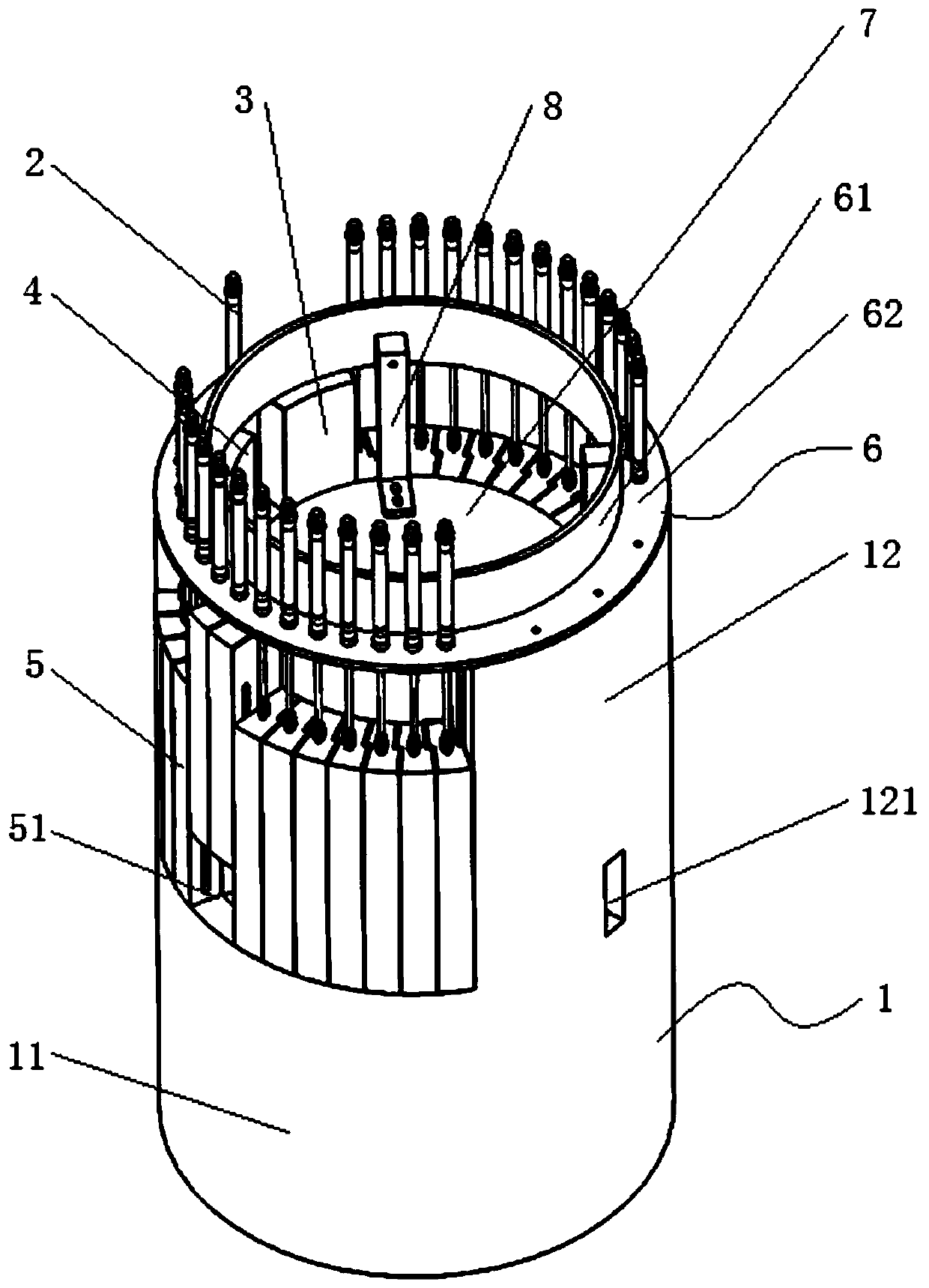
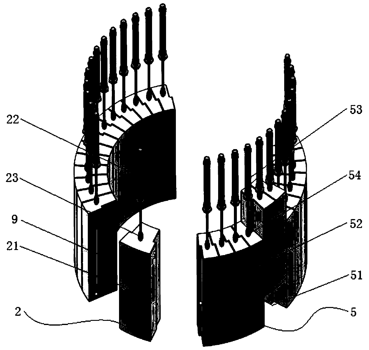
[0081] 1.1) If Figure 5 and Figure 6 As shown, the controller starts the air intake at the lower end of the 18th and 19th second cylinders 53 according to the calculation result of A2=75.4°, and passes through the 18th and 19th second cardan shafts 54 under the action of air pressure Lift the 18th and 19th second shielding blocks 52 to form an outgoing neutron channel 51 with the shielding body 1 .

[0082] 1.2) As the neutron ...

Embodiment 2

[0085] Embodiment 2: If the neutron analyzer take-off angle A2 is adjusted from -54.4 ° to the movement process of -102 °:

[0086] The take-off angle A2 of the neutron analyzer = -54.4°, calculated as follows:

[0087]

[0088] Ω=4

[0089]

[0090] satisfy:

[0091]

[0092] N1-Ω=9

[0093] N1-Ω-1=8

[0094] The take-off angle A2 of the neutron analyzer = -102°, calculated as follows:

[0095]

[0096] Ω=8

[0097]

[0098]satisfy:

[0099]

[0100] N1-Ω+1=6

[0101] N1-Ω=5

[0102] N1-Ω-1=4

[0103] 2.1) If Figure 7 and Figure 8 As shown, the controller starts the air intake at the lower end of the 8th and 9th second cylinder 53 cylinders according to the calculation result of A2=-54.4°, and passes through the 8th and 9th second cardan shafts under the action of air pressure 54 Lift the 8th and 9th second shielding blocks 52 to form an outgoing neutron channel 51 with the shielding body 1 .

[0104] 2.2) As the neutron analyzer rotates clockw...


PUM


Abstract

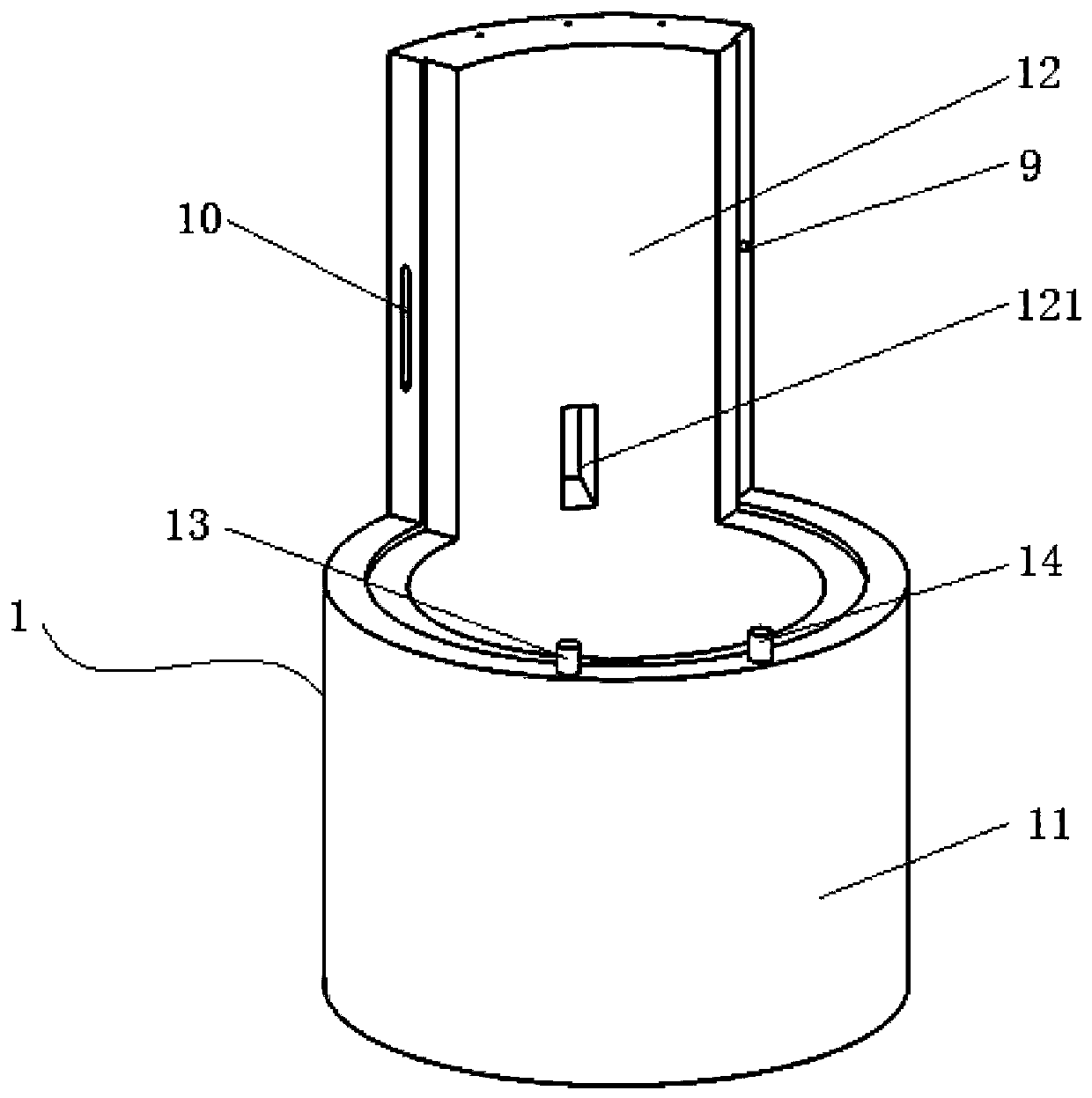
The invention relates to a neutron analyzer shielding device and an adjusting method thereof. The neutron analyzer shielding device is characterized by comprising a shielding body, a zero angle shielding block component, a first fixed support, a second fixed support, lifting shielding block components, a support body, an upper cover, connecting plates and a controller; the shielding body is an inner hollow column-like structure which is fixedly connected by a shielding cylinder portion and a sector shielding plate portion; an incident neutron channel is disposed on the sector shielding plate portion; the first fixed support, the zero angle shielding block component, the second fixed support and a plurality of lifting shielding block components are disposed on the top of the shielding cylinder portion; the top of the first fixed support, the second fixed support and the sector shielding plate portion are fixedly connected to the support body; the top of the upper cover is fixedly connected to the support body through a plurality of connecting plates; and the zero angle shielding block component and each lifting shielding block component are also electrically connected to the controller. The invention is widely applicable in the technical field of neutron scattering.

Description

technical field [0001] The invention relates to a neutron analyzer shielding device and an adjustment method thereof, and belongs to the technical field of neutron scattering. Background technique [0002] Neutron scattering spectrometers are often divided into elastic scattering spectrometers and inelastic scattering spectrometers. Among them, inelastic scattering spectrometers are composed of monochromators, sample stages, analyzers and detectors. The neutron beam is incident on the analyzer, and according to Bragg's law of diffraction, the analyzer reflects a neutron beam of one energy, which finally reaches the detector. The neutron energy emitted by the analyzer is often referred to as the final energy. Rotating the analyzer will cause the take-off angle A2 between the incident beam and the outgoing beam of the analyzer to change, and the energy of the outgoing neutrons will also change. In neutron scattering experiments, it is necessary to continuously adjust the tak...

Claims


Application Information

Patent Timeline
IPC IPC(8): G01N23/20008G01N23/207G01T3/02
CPCG01N23/20008G01N23/2073G01T3/02G01N2223/063G01N2223/106Y02E30/30
Inventor 张红霞程鹏徐大业刘娟娟汪晋辰鲍威
Owner RENMIN UNIVERSITY OF CHINA
Learn More