Image processing apparatus and method, and non-transitory computer-readable storage medium

a technology of image processing and computer-readable storage medium, which is applied in the direction of digital non-picture data transmission, color television details, television systems, etc., can solve problems affecting viewing experience and achieve the effect of maximum luminan

Active Publication Date: 2020-04-16
CANON KK
View PDF0 Cites 0 Cited by
  • Summary
  • Abstract
  • Description
  • Claims
  • Application Information

AI Technical Summary

Benefits of technology

[0011]In order to achieve the above object, an image processing apparatus of the present invention for processing image data obtained by an image capturing apparatus has one or more processors and / or circuitry which functions as: an output unit that outputs the image data obtained by the image capturing apparatus and maximum luminance information which is information for indicating a maximum luminance of the image data to an external device; an acquisition unit that acquire a maximum luminance that the image capturing apparatus is capable of handling; and a control unit that controls the output unit to output the maximum luminance acquired by the acquisition unit as the maximum luminance information.

Problems solved by technology

With such image processing, in the case where a plurality of images of the same main subject are continuously displayed, for example, the following problem arises when images whose maximum luminance within the image is higher than and lower than the displayable luminance of the display device are displayed together, even if the luminance of the main subject is the same.
That is, the luminance of the main subject that is displayed fluctuates up and down, adversely affecting the viewing experience.

Method used


Image

  • Image processing apparatus and method, and non-transitory computer-readable storage medium
  • Image processing apparatus and method, and non-transitory computer-readable storage medium
  • Image processing apparatus and method, and non-transitory computer-readable storage medium

Examples


first embodiment

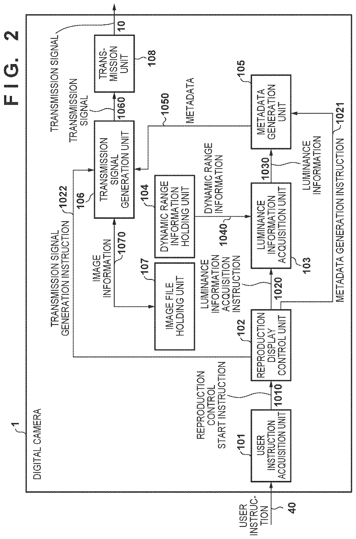
[0032]FIG. 2 is a block diagram representing the configuration of processing modules in the digital camera 1 of the first embodiment, and, for example, some or all the processing is constituted using a CPU, a memory and the like (not shown) that are included in the digital camera 1. In the first embodiment, a user instruction acquisition unit 101, a reproduction display control unit 102, a luminance information acquisition unit 103, a dynamic range information holding unit 104, a metadata generation unit 105, a transmission signal generation unit 106, an image file holding unit 107 and a transmission unit 108 are included as processing modules. Note that, in FIG. 2, processing modules that are unnecessary in describing the present embodiment are omitted.

[0033]The user instruction acquisition unit 101 consists of a user interface such as buttons, a touch panel and the like arranged on the digital camera 1, for example, for receiving instructions from the user and a processing unit th...

second embodiment

[0058]Next, a second embodiment of the present invention will be described. In the second embodiment, another external digital camera is connectable to the digital camera 1, and processing in the case of being able to receive and hold image files from a connected external digital camera will be described. Note that a mode in which image files are acquired via a portable recording medium may be adopted as a mode of acquiring image files from another digital camera 1. Hereinafter, an example will be described in which metadata is determined based on information on the digital camera that generated the image file.

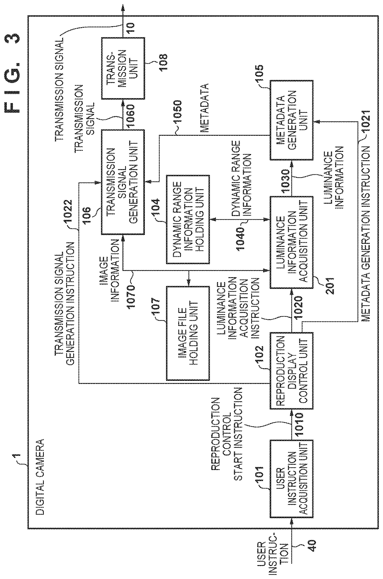
[0059]FIG. 3 is a block diagram representing the configuration of processing modules in a digital camera 1 of the second embodiment, and, for example, some or all the processing is constituted using a CPU, a memory and the like (not shown) that are included in the digital camera 1. The processing of the digital camera 1 in the second embodiment differs in the processing of a l...

third embodiment

[0066]Next, a third embodiment of the present invention will be described. In the first embodiment, an example in which metadata including information on a common maximum luminance is appended to all images in the digital camera 1 was described. In contrast, in the third embodiment, an example in which images are grouped and, for every group, the same metadata is appended to images included in the group will be described.

[0067]FIG. 5 is a block diagram representing the configuration of processing modules in a digital camera 1 of the third embodiment, and, for example, some or all the processing is constituted using a CPU, a memory and the like (not shown) that are included in the digital camera 1. The processing modules of the digital camera 1 in the third embodiment include a grouping processing unit 302, in comparison with the processing modules described with reference to FIG. 2, and, as a result, the processing of a reproduction display control unit 301, a luminance information ...


PUM


Abstract

An image processing apparatus of the present invention for processing image data obtained by an image capturing apparatus comprises one or more processors and/or circuitry which functions as: an output unit that outputs the image data obtained by the image capturing apparatus and maximum luminance information which is information for indicating a maximum luminance of the image data to an external device; an acquisition unit that acquires a maximum luminance that the image capturing apparatus is capable of handling; and a control unit that controls the output unit to output the maximum luminance acquired by the acquisition unit as the maximum luminance information.

Description

CROSS-REFERENCE TO RELATED APPLICATIONS[0001]This application is a Continuation of International Patent Application No. PCT / JP2018 / 021859, filed Jun. 7, 2018, which claims the benefit of Japanese Patent Application No. 2017-126515, filed Jun. 28, 2017, both of which are hereby incorporated by reference herein in their entirety.BACKGROUND OF THE INVENTIONField of the Invention[0002]The present invention relates to an image processing apparatus and method, and non-transitory computer-readable storage medium.Background Art[0003]Heretofore, there are technologies for transmitting a video signal to a display device such as a television from a video signal source that holds video content. In recent years, technologies for transmitting characteristics of video content (e.g., information on the maximum luminance of content, etc.) that are included in video content to a display device as metadata, together with video information from the video signal source, when transmitting video content, ...

Claims


Application Information

Patent Timeline
Patent Type & Authority Applications(United States)
IPC IPC(8): H04N5/235H04N7/025H04N5/243H04N5/57
CPCH04N7/025H04N5/243H04N5/2351H04N5/57H04N5/77H04N9/8205H04N21/4318H04N23/71H04N23/76
Inventor TAKAHASHI, RYOSUKE
Owner CANON KK
Why Eureka
Try Eureka