
Upright support bar

a support bar and support rod technology, applied in the direction of rod connection, building parts, fastening means, etc., can solve the problems of time-consuming and laborious, difficult to set the tension spring, etc., and achieve the effect of slow lowering, easy setting up and assembly, and better positioning

Active Publication Date: 2020-04-23
JYIN SHENG CO LTD HUATAN TOWNSHIP
View PDF4 Cites 0 Cited by
  • Summary
  • Abstract
  • Description
  • Claims
  • Application Information

AI Technical Summary

Benefits of technology

The present invention provides an upright support bar that is easy to assemble and has better positioning effect. It also has a structure for providing a buffering effect to the inner tube that is different from the prior art and provides a cushioning interference effect. The sliding block of the present invention can be moved on the mount between a first position and a second position so that the locking piece of the sliding block can be moved from the position in abutment against the finger grip of the button to a direction away from the button. The sliding block is easy to set up and assemble. In addition, by the elastic action of the steel ball on the holes of the inner tube, an interference buffering effect during the elastic action can be provided, so that the inner tube can be slowly lowered when falling, without damaging the user.

Problems solved by technology

However, the safety ejector must be fitted with a tension spring, but because of the small space, it is not easy to set the tension spring.
Moreover, when the safety ejector is installed, the safety ejector is required to be pressed by one hand, and a tool must be used to drive a nut to complete the connection, which is quite time-consuming and labor-intensive.

Method used


Image

  • Upright support bar
  • Upright support bar
  • Upright support bar

Examples


Embodiment Construction

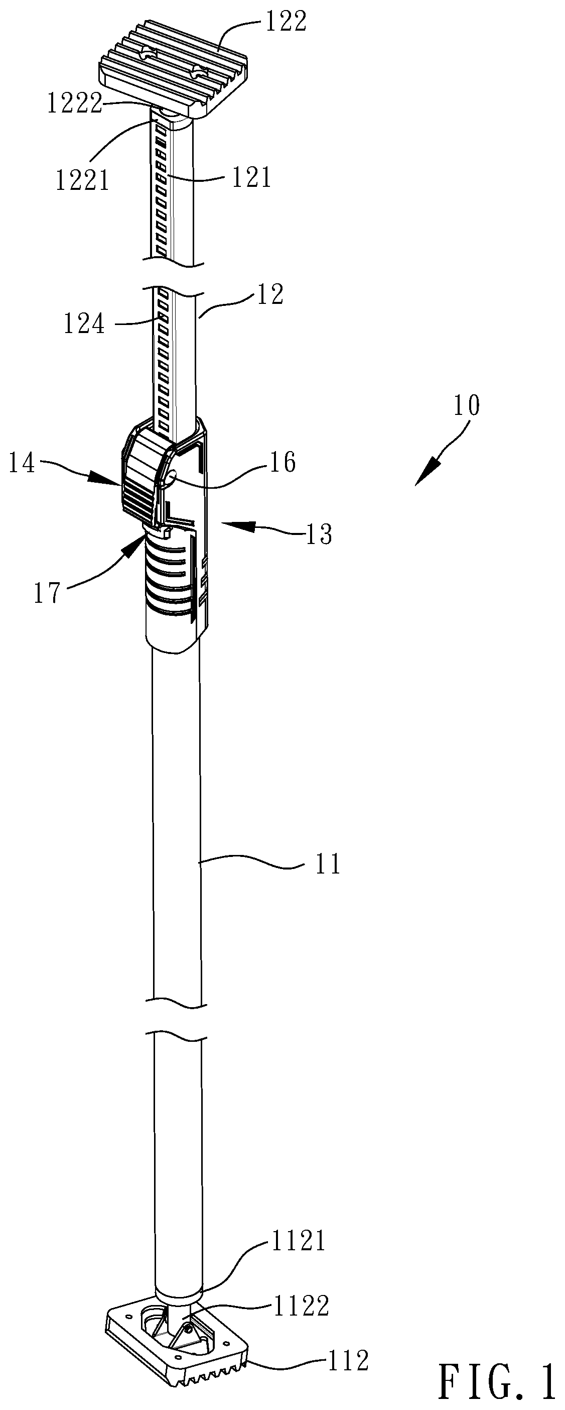
[0017]Referring to FIGS. 1-8, an upright support bar 10 in accordance with the present invention can be placed between the ceiling and the ground for hanging an object (bicycle or other.) (not shown).

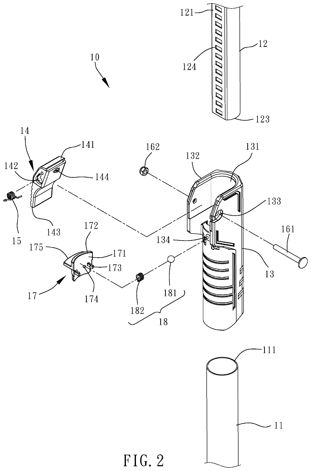
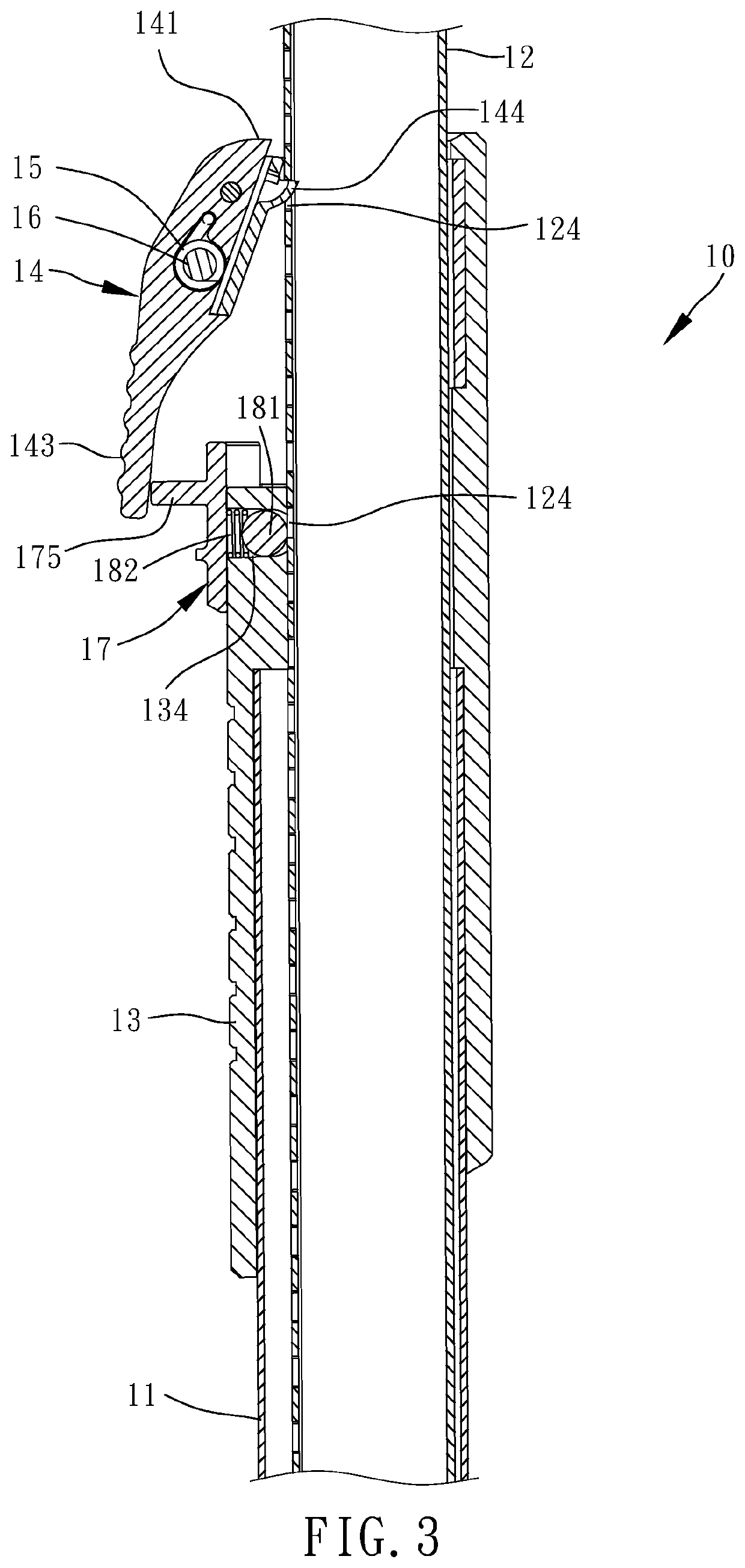
[0018]The upright support bar 10 comprises an outer tube 11, an inner tube 12, a mount 13, a button 14, a torsion spring 15, a pivot device 16, a sliding block 17 and an elastic damping device 18.

[0019]The outer tube 11 is a long round tube, having one end thereof terminating in a nesting end 111 and an opposite end thereof mounted with a foot member 112. The foot member 112 is locked with the outer tube 11 by a plug 1121 and a screw rod 1122. Because it is a conventional knowledge and is not the main technical features of the present invention, it will not be described here.

[0020]The inner tube 12 is also a long round tube but has a flat surface 121. The inner tube 12 has one end thereof mounted with a foot member 122, and an opposite end thereof terminating in an insertion end 123. Th...


PUM


Abstract

An upright support bar includes a mount disposed at the pivotal joint between an outer tube and an inner tube, a button pivoted to the mount and providing an actuation end, a finger grip and a latching portion so arranged that when the actuation end is biased downward, the latching portion is engaged in one of a series of holes of the inner tube, and a sliding block with a locking piece mounted on the mount movable relative to the mount between a first position where the locking piece is abutted against the finger grip to lock the button and a second position where the locking piece is released from the finger grip to unlock the button.

Description

BACKGROUND OF THE INVENTION1. Field of the Invention[0001]The present invention relates to a retractable support bar technology and more particular, to an upright support bar that has better positioning effect.2. Description of the Related Art[0002]Taiwan Patent No. 553332 discloses an improved retractable support bar positioning structure, which comprises an inner tube and an outer tube coupled together. The outer end of the outer tube and the outer end of the inner tube are respectively provided with a foot member. The foot members can be stopped between two planes (between the ceiling and the ground, or between two walls). The inner tube has a plurality of holes spaced along the length. A mount is disposed at the opposing inner end of the outer tube that receives the inner tube. An elastic button is mounted on the mount. The head of the elastic button can be engaged into one hole of the inner tube to lock the combined length of the inner tube and the outer tube. The retractable s...

Claims


Application Information

Patent Timeline
Patent Type & Authority Applications(United States)
IPC IPC(8): F16B7/10
CPCF16B7/105E04G5/06E04G25/068F16B7/10
Inventor TSAI, YU-LUNG
Owner JYIN SHENG CO LTD HUATAN TOWNSHIP
Learn More