
Sound output apparatus

a technology of sound output and auxiliary components, which is applied in the manufacture/assembly of earpieces/earphones, electrical transducers, multiple transducers, etc., can solve the problems of small wearable sound reproduction apparatuses such as earphones, limited low-frequency reproduction capability, and difficult to arrange the large driver near the entrance of the ear canal of a listener

Active Publication Date: 2020-04-30
SONY CORP
View PDF0 Cites 32 Cited by
  • Summary
  • Abstract
  • Description
  • Claims
  • Application Information

AI Technical Summary

Benefits of technology

The present invention is a sound output device that can be worn near the ear of a listener and produce sound over a wide range of frequencies. This technology has several benefits, which are not limited to what is described here. In addition to providing a better listening experience, this device can help to reduce noise and provide a more immersive sound experience.

Problems solved by technology

Small wearable sound reproduction apparatuses, such as earphones, have a limited low-frequency reproduction capability.
However, there is a problem that it is difficult to arrange the large driver near the entrance of the ear canal of a listener.
For example, in a case of an earphone that fits into the ear concha, it is difficult to arrange the large driver.
However, a sound guiding duct that extends from the rear of the ear to the vicinity of the ear hole tends to be long, and there is a concern that the attenuation of the high-frequency band in the duct will increase.
Furthermore, a sharp dip may occur in part of a frequency band in some cases due to the acoustic resonance of the sound guiding duct.

Method used


Image

  • Sound output apparatus
  • Sound output apparatus
  • Sound output apparatus

Examples


Embodiment Construction

[0056]Hereinafter, the embodiments of the technology disclosed in this specification will be described in detail with reference to the drawings.

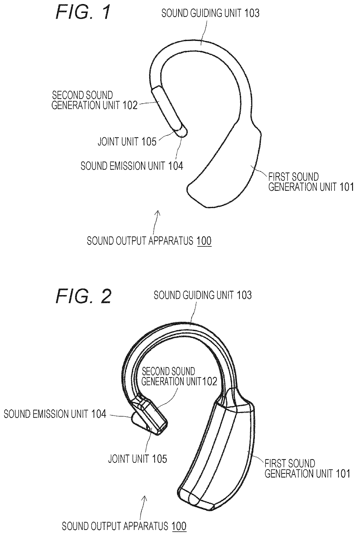
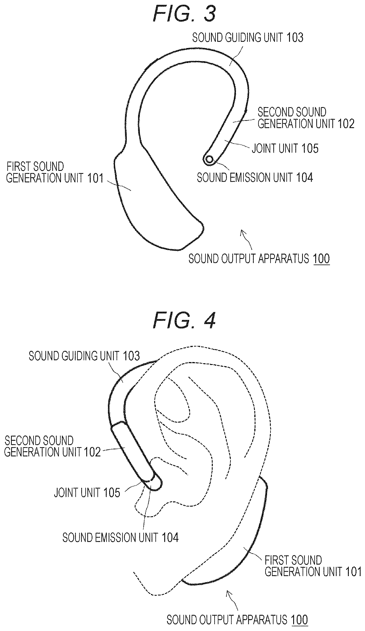
[0057]FIGS. 1 to 3 show exterior configuration examples of a sound output apparatus 100 according to one embodiment of the technology disclosed in this specification. As will be described later, the sound output apparatus 100 is basically used by being worn on the auricle of a listener who is a listener.

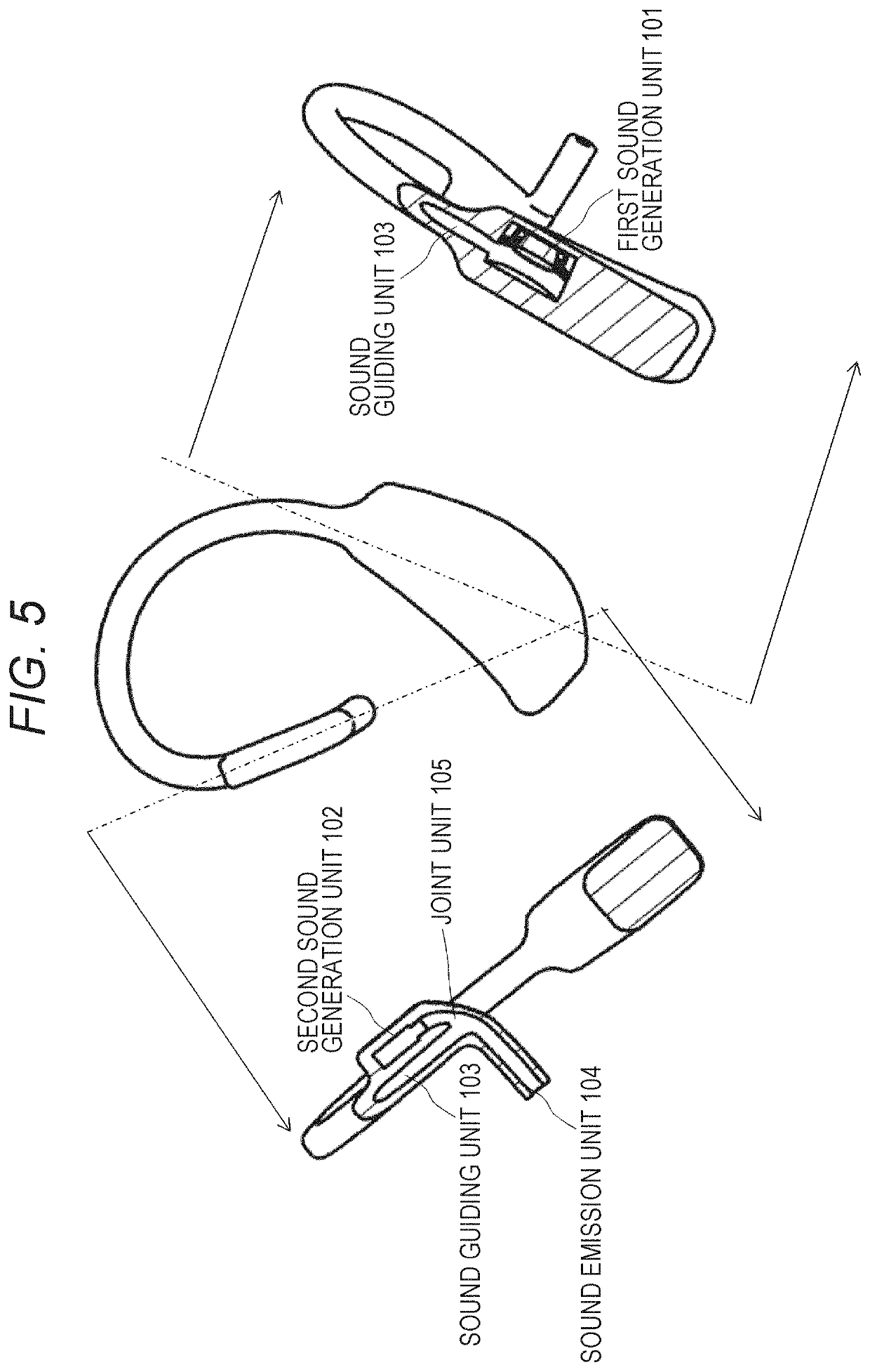
[0058]The illustrated sound output apparatus 100 includes a first sound generation unit 101, a second sound generation unit 102 and a sound guiding unit 103. The first sound generation unit 101 mainly generates a low-frequency sound, and the second sound generation unit 102 mainly generates a high-frequency sound. The sound guiding unit 103 propagates the respective acoustic signals outputted from the first sound generation unit 101 and the second sound generation unit 102 to the vicinity of the entrance of the ear canal of the listener. The ...


PUM


Abstract

Provided is a sound output apparatus that is used by being worn in the vicinity of the ear of a listener and is capable of outputting sound over a wide frequency band.The sound output apparatus includes: a first sound generation unit configured to generate a low frequency band; a sound guiding unit with a hollow structure, having one end coupled to the first sound generation unit, and the other end as a sound emission unit including an open end; and a second sound generation unit that is disposed at a place closer to the sound emission unit than the first sound generation unit and generates a high frequency band. It is preferable that the sound guiding unit have a joint unit that takes in the sound from the second sound generation unit and a section from the joint unit to the sound emission unit have a low impedance.

Description

TECHNICAL FIELD[0001]The technology disclosed in this specification relates to a sound output apparatus used by being worn in the vicinity of the ear of a listener.BACKGROUND ART[0002]Along with the emergence of high-resolution audio and the like in recent years, a wide band of reproducible frequency has been demanded for devices that reproduce content related to sound such as music.[0003]Small wearable sound reproduction apparatuses, such as earphones, have a limited low-frequency reproduction capability. Thus, in order to enhance the sensitivity to low-frequency reproduction, it is necessary to mount a large driver. However, there is a problem that it is difficult to arrange the large driver near the entrance of the ear canal of a listener. For example, in a case of an earphone that fits into the ear concha, it is difficult to arrange the large driver.[0004]For example, for a sound-isolating earphone that is used in a state where the ear hole is being sealed, an earphone has been ...

Claims


Application Information

Patent Timeline
Patent Type & Authority Applications(United States)
IPC IPC(8): H04R1/10H04R23/02H04R3/14H04R1/26
CPCH04R1/105H04R2225/00H04R1/26H04R1/1066H04R23/02H04R1/1016H04R3/14H04R1/1075
Inventor SHINMEN, NAOKIIGARASHI, GOASADA, KOHEI
Owner SONY CORP
Learn More