Bookbinding machine

a book binding machine and book binding technology, applied in the field of book binding machines, can solve the problems of imposing a heavy burden on users, requiring a long time and considerable labor, and unsatisfactory adhesion force, and achieve the effect of reducing the workload of users

Active Publication Date: 2020-05-14
HORIZON INTERNATIONAL INC
View PDF9 Cites 0 Cited by
  • Summary
  • Abstract
  • Description
  • Claims
  • Application Information

AI Technical Summary

Benefits of technology

[0021]According to the present invention, the rotational speed coefficient depending on both the thickness of the book block to be bound and the set value of the conveying speed of the clamper is calculated using the first function which defines the relationship between the thickness of the book block and the rotational speed coefficient of the pump (representing the percent change of the rotational speed of the pump relative to the reference rotational speed of the pump) and the second function which defines the relationship between the conveying speed of the clamper and the rotational speed coefficient of the pump, and furthermore the set value of the rotational speed of the pump is calculated based on both the rotational speed coefficient and the reference rotational speed, and then the initial setting of the rotational speed of the pump is automatically performed according to the set value of the rotational speed.
[0022]Thus an easy and quick initial setting of the nozzle type adhesive application mechanism is achieved so that user's workload is reduced considerably.

Problems solved by technology

The EVA adhesive can be easily treated because it infinitely repeats the cycle of melting by heating and hardening by cooling on the one hand, and has a defect of unsatisfied adhesion force on the other hand.
However, the preparation of this table is achieved by bookbinding actually while changing combinations of the thickness of the book block, the rotational speed of the pump and the conveying speed of the clamper and so on in various ways, which requires a long time and considerable labor and imposes a heavy burden on the users.

Method used


Image

  • Bookbinding machine
  • Bookbinding machine
  • Bookbinding machine

Examples


Embodiment Construction

[0029]A preferred embodiment of the present invention will be explained below with reference to the accompanying drawings.

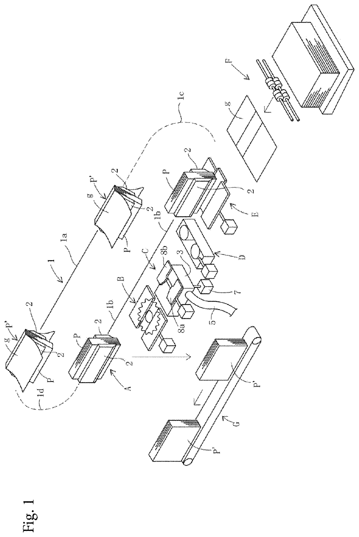
[0030]FIG. 1 is a perspective view schematically illustrating a configuration of a bookbinding machine according to an embodiment of the present invention.

[0031]Referring to FIG. 1, according to the present invention, one or more (in this embodiment, four) clampers 2 adapted to grip a book block P to be bound while keeping the book block P in a standing state are arranged so as to be movable along a predetermined path 1.

[0032]In this embodiment, the path 1 of the clampers 2 is a loop path composed of horizontal upper and lower linear path portions 1a, 1b which are spaced from each other in a vertical plane and arcuate path portions 1c, 1d which connect ends of the upper and lower linear path portions 1a, 1b.

[0033]Although not shown in the drawings, a guide is arranged along the path 1. The clampers 2 are slidably attached to the guide and movable along the path ...


PUM


Abstract

A bookbinding machine calculates a rotational speed coefficient, which represents the percent change of a rotational speed of a pump 6 relative to the reference rotational speed of the pump, depending on a thickness of a book block P to be bound and a conveying speed of a clamper by use of a first function defining a relationship between the thickness of the book block and the rotational speed coefficient and a second function defining a relationship between the rotational speed coefficient and the conveying speed of the clamper, calculates the set value of the rotational speed of the pump based on the rotational speed coefficients and the reference rotational speed, and sets the rotational speed of the pump according to the set value of the rotational speed.

Description

TECHNICAL FIELD[0001]The present invention relates to a bookbinding apparatus, in particular, a perfect bookbinding machine provided with a nozzle type adhesive application mechanism.BACKGROUND ART[0002]In perfect bookbinding machines, EVA (Ethylene Vinyl Acetate) hot-melt adhesive (referred to as “EVA adhesive” hereinafter) is generally used. The EVA adhesive can be easily treated because it infinitely repeats the cycle of melting by heating and hardening by cooling on the one hand, and has a defect of unsatisfied adhesion force on the other hand.[0003]Hence PUR (Poly Urethane Reactive) hot-melt adhesive (referred to as “PUR adhesive” hereinafter), whose adhesion force is much stronger than that of the EVA adhesive, has attracted attention in recent years. The PUR adhesive has a characteristic that it hardens by reacting with water contained in air or paper and never softens even when heated if once it hardens.[0004]Accordingly, in a bookbinding machine using the PUR adhesive, an a...

Claims


Application Information

Patent Timeline
Patent Type & Authority Applications(United States)
IPC IPC(8): B42C9/00B42C19/08
CPCB42C9/0006B42C19/08B05C5/0204B05C11/1021B05C11/1023B42C9/00
Inventor TAGO, SHIGEYOSHIFUKUDA, SHIGENOBUKITAYAMA, SHINYAFUJIWARA, KOSUKE
Owner HORIZON INTERNATIONAL INC
Why Eureka
Try Eureka