This helps you quickly interpret patents by identifying the three key elements:
Problems solved by technology
Method used
Benefits of technology
Benefits of technology
The elevatable supporting device has the benefits of having fewer parts, being straightforward to operate, providing stable support, and having a long-life energy storage element.
Problems solved by technology
However, the conventional supporting device has the disadvantages of higher accuracy requirements of the curved surface of the cam and shorter lifetime of the energy storage element.
Method used
Image
Click on the blue label to locate the original text in one second.
Reading with bidirectional positioning of images and text.
Examples
first embodiment
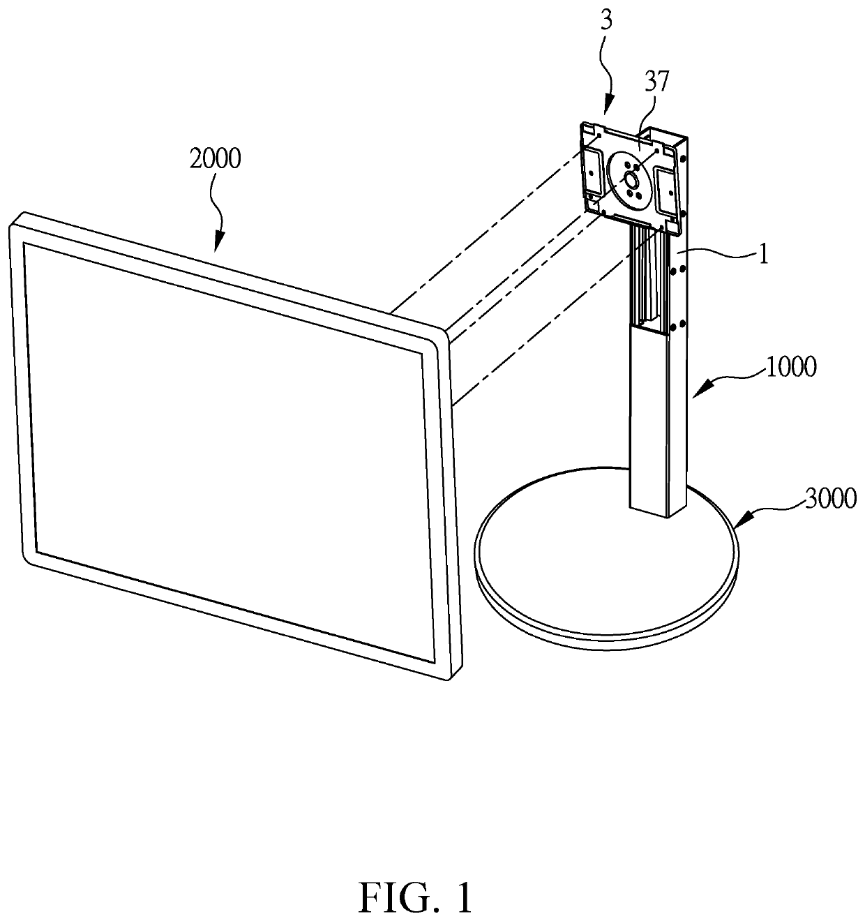
[0049]Please refer to FIG. 1, which illustrates a perspective view of an elevatable supporting device 1000, a base 3000, and a display 2000 of the present invention. The elevatable supporting device 1000 of the present invention is utilized for bearing the display 2000; however, the elevatable supporting device 1000 does not have to be connected to a base 3000. In other embodiments, the elevatable supporting device 1000 can be disposed onto a surface of a wall, on a desktop, or be connected to other devices, which is not particularly limited.
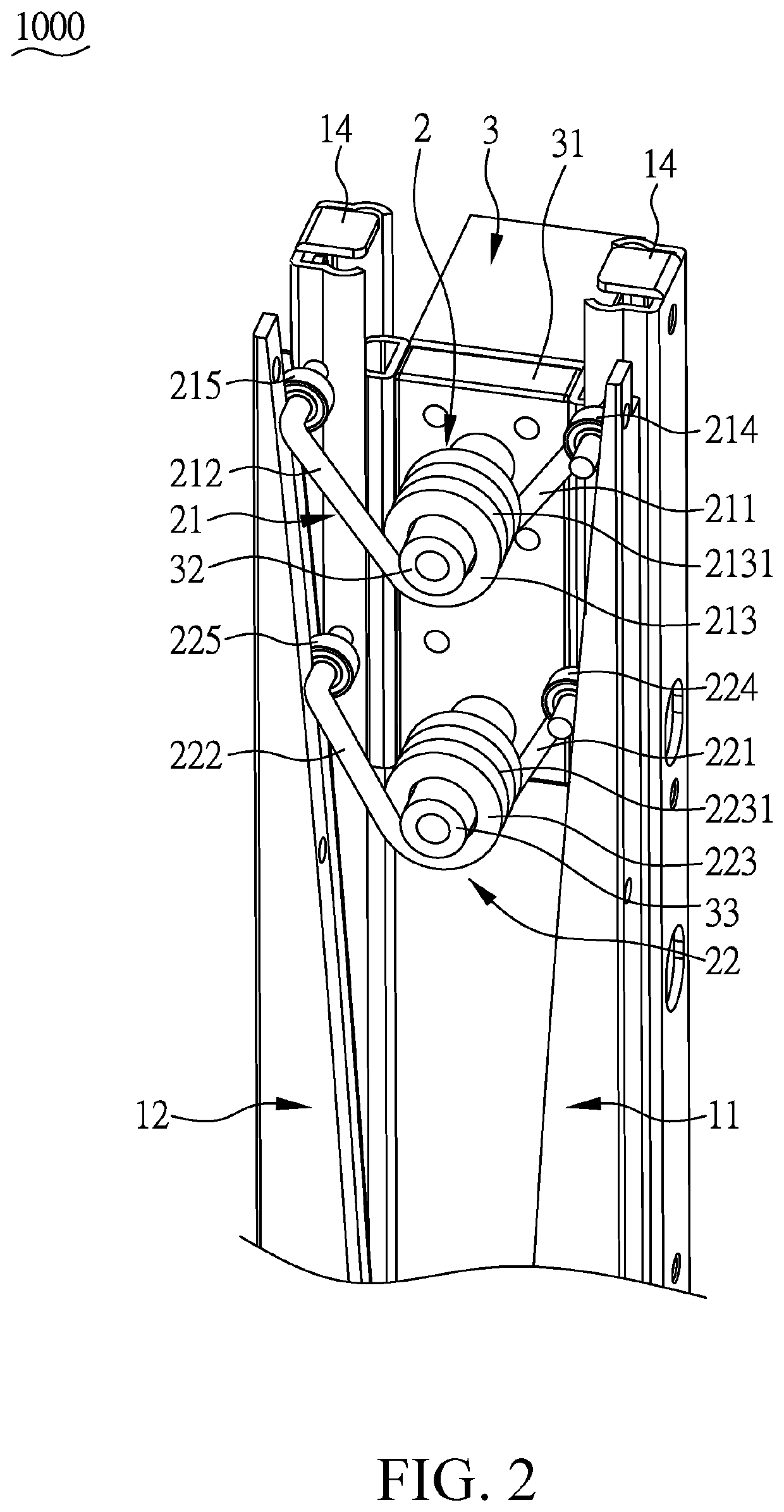
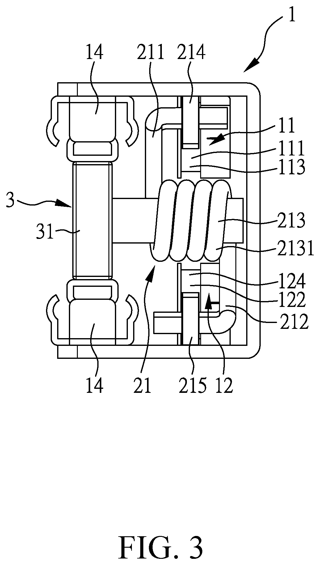
[0050]Please refer to FIG. 2, FIG. 3, FIG. 4, and FIG. 5, which illustrate partial views and a top view of the elevatable supporting device 1000 of the first embodiment of the present invention. The elevatable supporting device 1000 comprises an upright 1, an energy storage unit 2, and a bearing module 3. The upright 1 extends along a first axis X and includes a first sliding structure 11, a second sliding structure 12 which is non-parallel to t...
second embodiment
[0070]Please refer to FIG. 8, FIG. 9, and FIG. 10 illustrating the partial perspective view of two different viewing angles and the top view of the elevatable supporting device 1000 of the present invention.
[0071]In the present embodiment, the energy storage unit 2 includes three energy storage elements; however, in other embodiments, the number of the energy storage element may be two, three, or more than three. The present embodiment exemplifies three energy storage elements in an energy storage unit. However, the following description will focus on two of the energy storage elements, the structure and the operation principle of the third energy storage element are similar to the first and the second energy storage elements; therefore, the detailed descriptions of the third energy storage element are omitted. In addition, the first sliding structure 11 includes three sliding surfaces, and the second sliding structure 12 includes three sliding surfaces. The first sliding surface 11...
third embodiment
[0074]Please refer to FIG. 11 and FIG. 12 illustrating the rear partial perspective view and the top view of the elevatable supporting device 1000 of the present invention.
[0075]The operation principle of the present embodiment is similar to that of the first embodiment, one difference between them is that the concave portion and the convex portion in the first embodiment are omitted, and another difference between them is that the energy storage unit 2 includes two V-shaped elastic steel plates. For example, each of the V-shaped elastic steel plates may be made of a flat spring, wherein each of the connecting sections having a pre-opening angle is formed by bending the elastic plate. Different from the torsional spring utilized in the first embodiment, the connecting sections of the energy storage elements in the present embodiment do not include winding portions, so that the energy storage unit 2 and the bearing module 3 are not actuated together through the winding portions set o...
PUM
Abstract
An elevatable supporting device for bearing a display is provided. The elevatable supporting device comprises an upright, an energy storage element, and a bearing module. The upright includes a first sliding structure and a second sliding structure which is non-parallel to the first sliding structure. The energy storage element abuts against the first sliding structure and the second sliding structure and includes a first arm providing a first resistance and a second arm providing a second resistance. A first included angle is defined between the first arm and the second arm. When the energy storage element moves from the highest position to the lowest position, the first included angle decreases so that one of the first resistance and the second resistance may increase in order to maintain a total effective resistance along the first axis. Accordingly, the display may be able to stop at any position between the highest position and the lowest position.
Description
CROSS REFERENCE TO RELATED APPLICATION[0001]This application claims the benefit of U.S. Provisional Application Ser. No. 62 / 758,034 filed on Nov. 9, 2018. The entirety of the Application is incorporated herein by reference.BACKGROUND OF THE INVENTION1. Field of the Invention[0002]The present invention relates to a supporting device, more particularly, to an elevatable supporting device for bearing a display.2. Description of Related Art[0003]U.S. Pat. No. 7,506,853 disclosed a supporting device for bearing a display, which includes a carrier, a sliding module, an upright, a base, and an energy storage element. The base is disposed on a working surface, the upright is disposed on the base and has a cam, the sliding module is disposed on the upright, and the carrier is disposed to connect to a display. The display and the carrier can move upward and downward with respect to the upright through the sliding module. When the display moves up and down, the energy storage element is actuat...
Claims
Application Information
Patent Timeline
Application Date:The date an application was filed.
Publication Date:The date a patent or application was officially published.
First Publication Date:The earliest publication date of a patent with the same application number.
Issue Date:Publication date of the patent grant document.
PCT Entry Date:The Entry date of PCT National Phase.
Estimated Expiry Date:The statutory expiry date of a patent right according to the Patent Law, and it is the longest term of protection that the patent right can achieve without the termination of the patent right due to other reasons(Term extension factor has been taken into account ).
Invalid Date:Actual expiry date is based on effective date or publication date of legal transaction data of invalid patent.

