Powered emergency released coupling control and monitoring system

Active Publication Date: 2019-12-19
MANN TEKNIK
View PDF0 Cites 1 Cited by
  • Summary
  • Abstract
  • Description
  • Claims
  • Application Information

AI Technical Summary

Benefits of technology

[0011]In case of a separate pressure tank for the pilot pressure gaseous media, the gaseous media will flow to the actuation line via the pressurizable chamber which results in a simple and reliable system with few components.
[0012]Thanks to the coupling according to the invention, wherein a pair of annular seals, preferably lip seals, are arranged on opposite sides of an annular seal supporting

Problems solved by technology

Without a hose rupture valve, the consequences of such events can b

Method used


Image

  • Powered emergency released coupling control and monitoring system
  • Powered emergency released coupling control and monitoring system
  • Powered emergency released coupling control and monitoring system

Examples


Example

[0034]The function of the control and monitoring system according to the first embodiment of the invention will now be described.

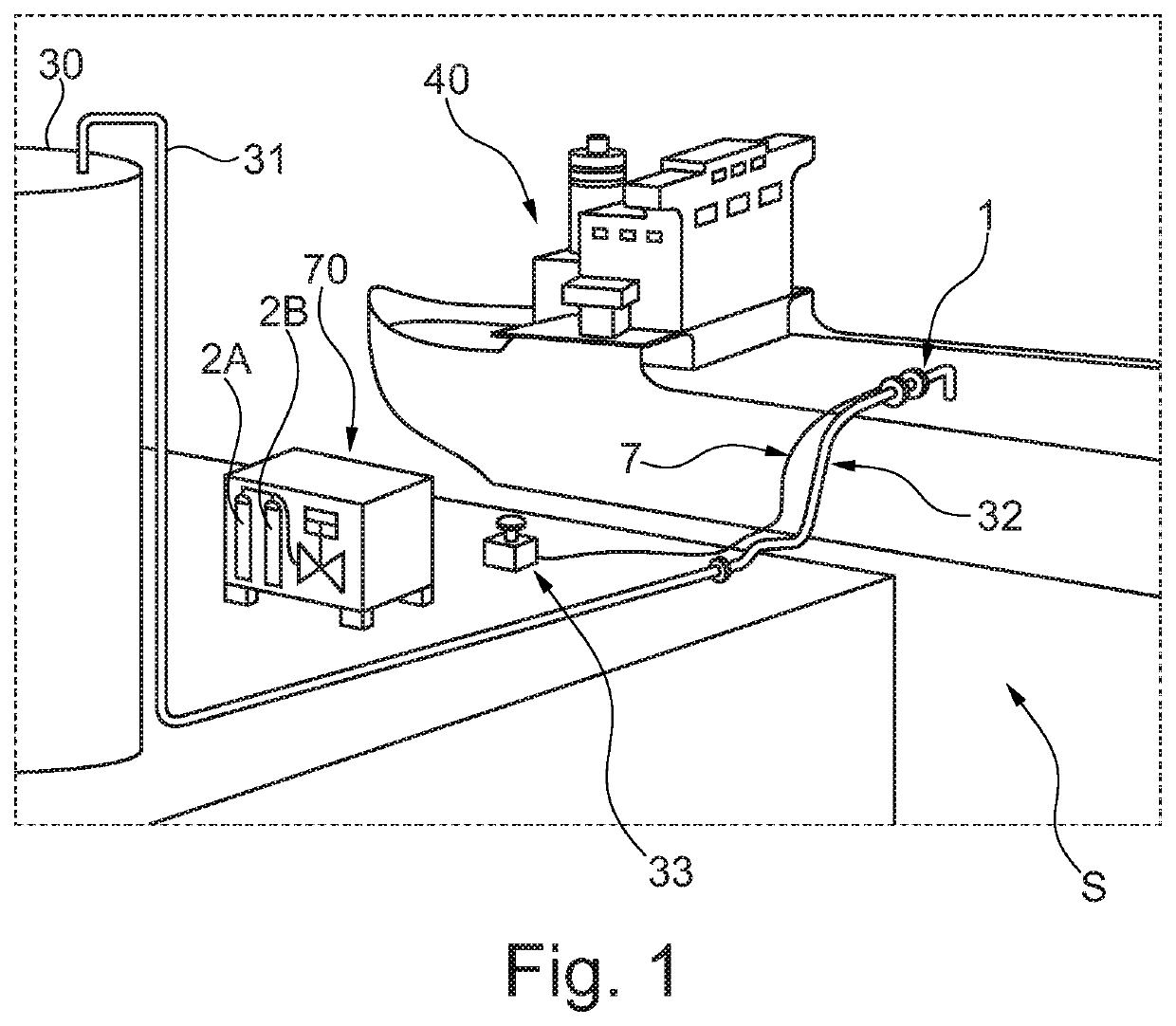
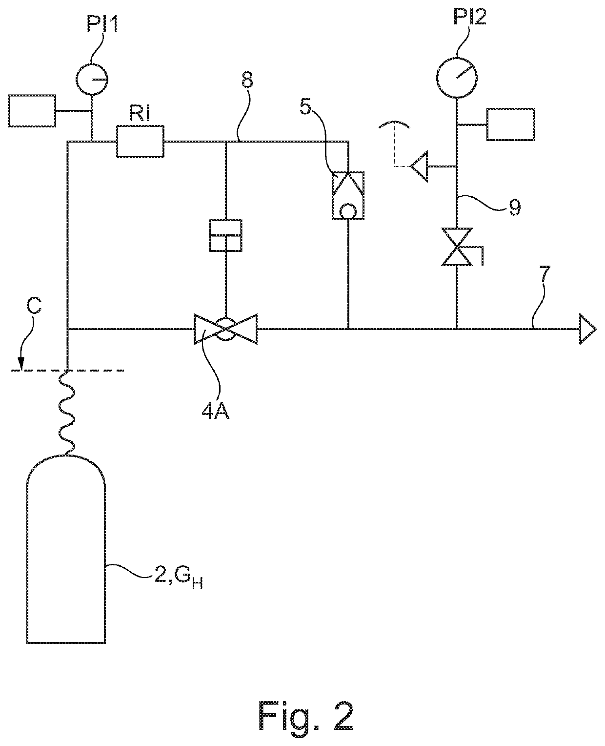
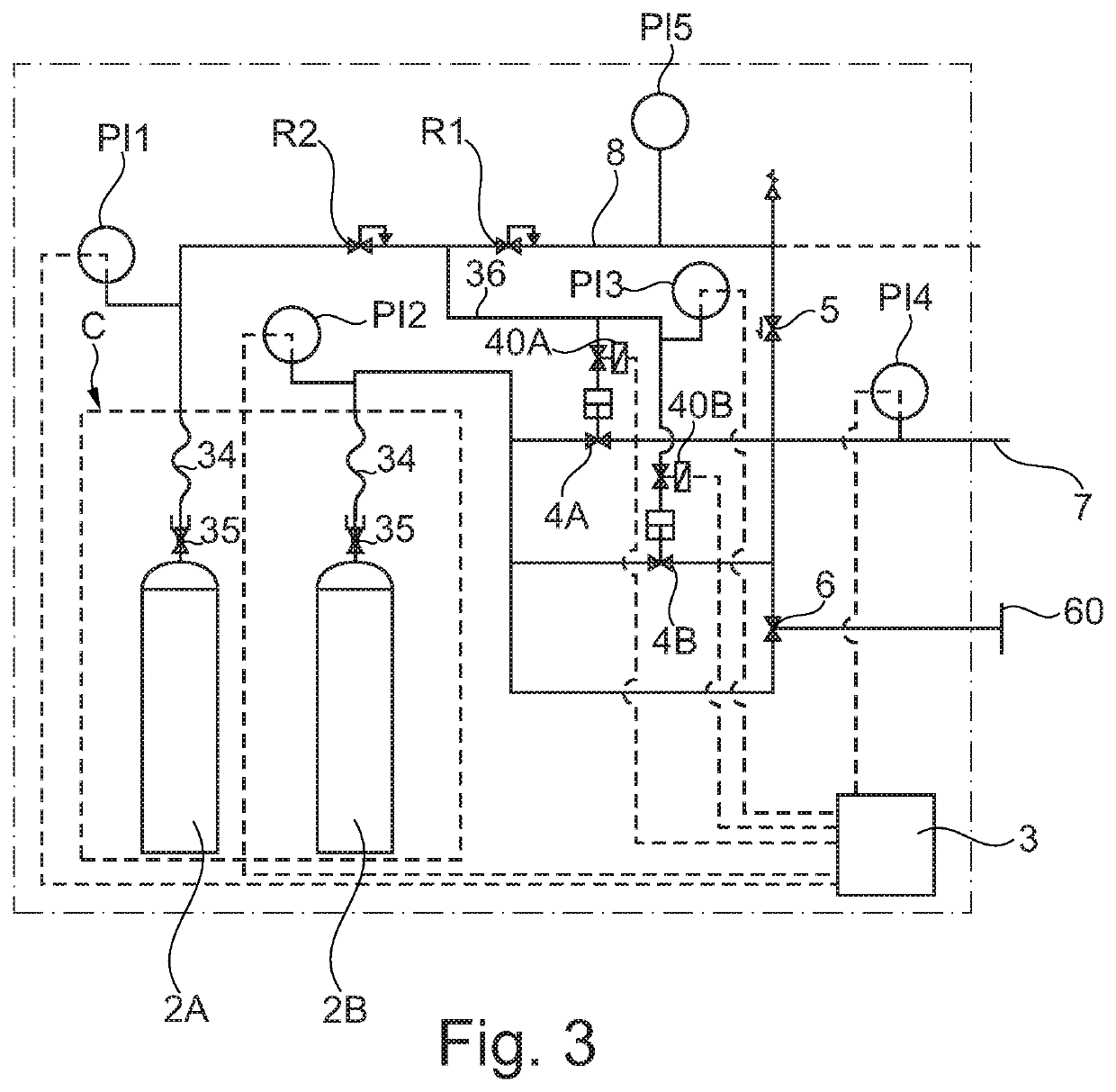
[0035]Before the fueling operation is commenced, a tightness control of the actuation line 7, its associated components and the PERC 1 is performed. High pressure nitrogen gas, typically 150-200 bar, from the high pressure gas cylinder 2 is distributed to the actuation line 7 and the monitoring line 8. Before and during normal operation, the actuation device 4A is closed so high pressure nitrogen gas will not pass the actuation device 4A toward the PERC 1. Instead, high pressure nitrogen gas flows into the monitoring line 7 where a first pressure indicator PI1 controls the actual pressure. Should the pressure not be sufficient, i.e. lower than what is required to separate the PERC 1 in case of emergency, a signal is given which alerts an operator and / or prevents the fueling operation to be started. Thereafter, the first pressure regulator R1 reduces the hi...


PUM


Abstract

The present invention relates to a pneumatically, high pressure gas powered emergency release coupling control and monitoring system (S) comprising a powered emergency released coupling (1) arranged in a fluid-supply line (32) for conveying hazardous fluids, said powered emergency released coupling (1) comprising a couple of coupling members (10, 11) provided with mating faces (10A, 11A) for sealing engagement of the coupling members (10, 11) and formation of a pressurizable chamber (12) between said coupling members (10, 11), said system (S) comprising an actuation line (7) connected at its one end to the pressurizable chamber (12) and at its other end to a source (C) of high pressure gaseous media (GH), preferably high pressure nitrogen gas, an first actuating device (4A, 4B) arranged in the actuation line (7), wherein said system (S) provides a gaseous media at a pilot pressure level to said pressurizable chamber (12) and to said actuation line (7) in a position downstream the first actuation device (4A, 4B) or via said pressurizable chamber (12) for detection of any leakage of gas in the control and monitoring system (S), said pilot pressure gaseous media preferably being low pressure nitrogen gas. The invention further relates to a pneumatically, high pressure gas powered emergency release coupling (1) and a control and monitoring method for such a system (S).

Description

TECHNICAL FIELD[0001]The present invention relates to a pneumatically, high pressure gas powered emergency release coupling control and monitoring system comprising a powered emergency released coupling (PERC) arranged in a fluid-supply line for conveying hazardous fluids, said powered emergency released coupling comprising a couple of coupling members provided with mating faces for sealing engagement of the coupling members and formation of a pressurizable chamber between said coupling members, an actuation line connected at its one end to the pressurizable chamber and at its other end to a source of high pressure gaseous media, preferably high pressure nitrogen gas, an first actuating device arranged in the actuation line. The invention further relates to a pneumatically, high pressure gas powered emergency release coupling (PERC) and a control and monitoring method for such a system.STATE OF THE ART[0002]Breakaway Couplings (BAC) and Emergency Release Couplings (ERC) ensure a saf...

Claims


Application Information

Patent Timeline
IPC IPC(8): F16L55/10F16L29/04B63B27/24F17C5/00
CPCB63B27/24F17C2250/072F16L29/04F17C5/007F16L55/1007F16L55/1015B67D7/3218B67D9/00F16L55/1022
Inventor LILLIESKÖLD, JOHANKOPPLIN, GERHARDADAMSSON, FREDRIKBÄCKSTRÖM, MARKUS
Owner MANN TEKNIK
Why Eureka
Try Eureka