One of the most difficult and challenging aspects of implantable devices has been their packaging and encapsulation to not only protect the internal components from the relatively harsh biological environments in which they reside, but to do so while providing a degree of meaningful communication between the internal components and the outside world through the use of a remote reading device.
Each of these systems are for the most part susceptible to damage by certain conditions found in the testing environment, including excessive
moisture or fluids, salts, acids, and high temperatures.
When such sensors are implanted within the body of a patient, if not suitably protected, the operative
electronics and other delicate components of the sensor (including the supporting components) will quickly become in contact with some hazardous elements.
Over time these elements can easily corrode and otherwise degrade the onboard components or the electrical connections, directly affecting the operation and reliability of the particular sensor.
Titanium, stainless steel and glass housings are typical for long-term, human-implanted devices because they are proven to effectively protect against harsh environments for long periods of time and are biocompatible.
One problem with using any material for the housing that requires heat to create a
hermetic seal (particularly
metal or plastic) is that during the heating and subsequent cooling the housing material expands and contracts.
This
temperature gradient typically changes the volume and pressure within the housing and potentially introduces mechanical stress to any of the delicate onboard sensors.
This may be acceptable for some applications, but if the housing contains pressure-measuring sensors, for example, the unpredictable expansion of the housing material and the introduction of mechanical stress will invariably affect the integrity and accuracy of the
pressure sensor.
Unfortunately, even these low temperatures and the above-mentioned
anodic bonding techniques can often result in residual mechanical stress trapped within the sensor membrane.
As a result, the
implant device cannot be completely isolated from its surroundings.
Unfortunately, although the
communication link offered by this direct-connect method is usually very effective, it has been proven very difficult to provide a reliable and effective seal within the bore around the
electrical conduit.
Before the useful life of the
implant has been reached, the bore is a
common point of a breach-failure of the entire implant.
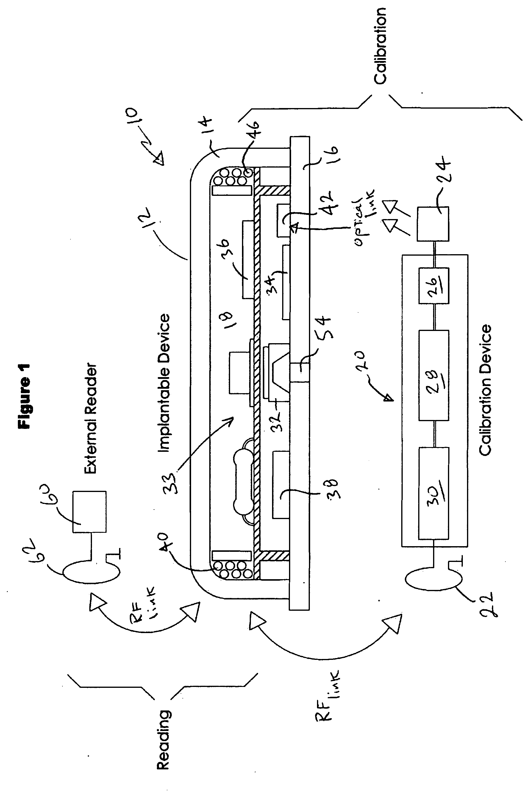
Unfortunately, providing two-way
wireless communication between a remote reader and an
implanted device requires
telemetry circuitry that is relatively expensive, consumes additional power and takes up precious real estate within the housing.
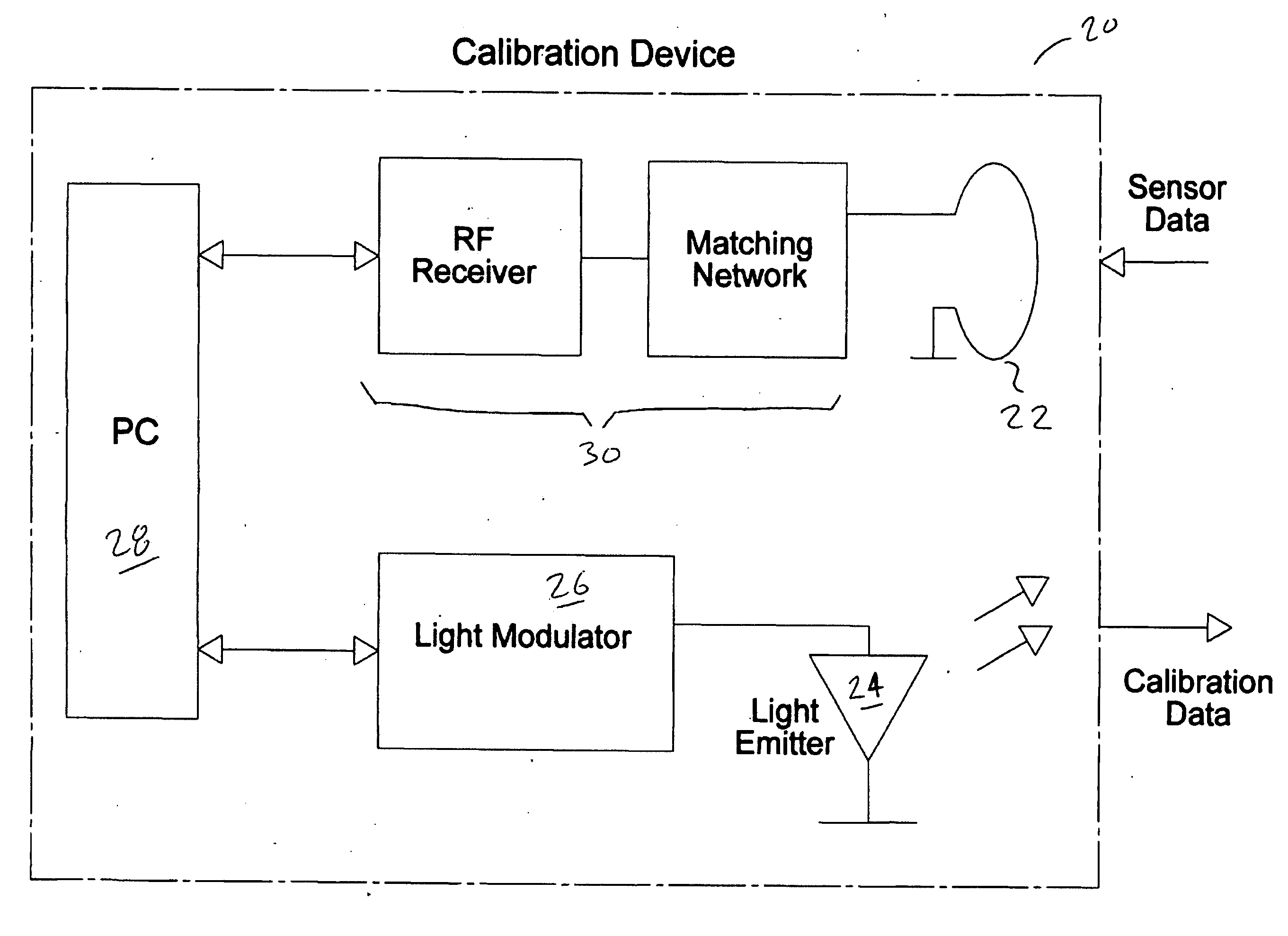
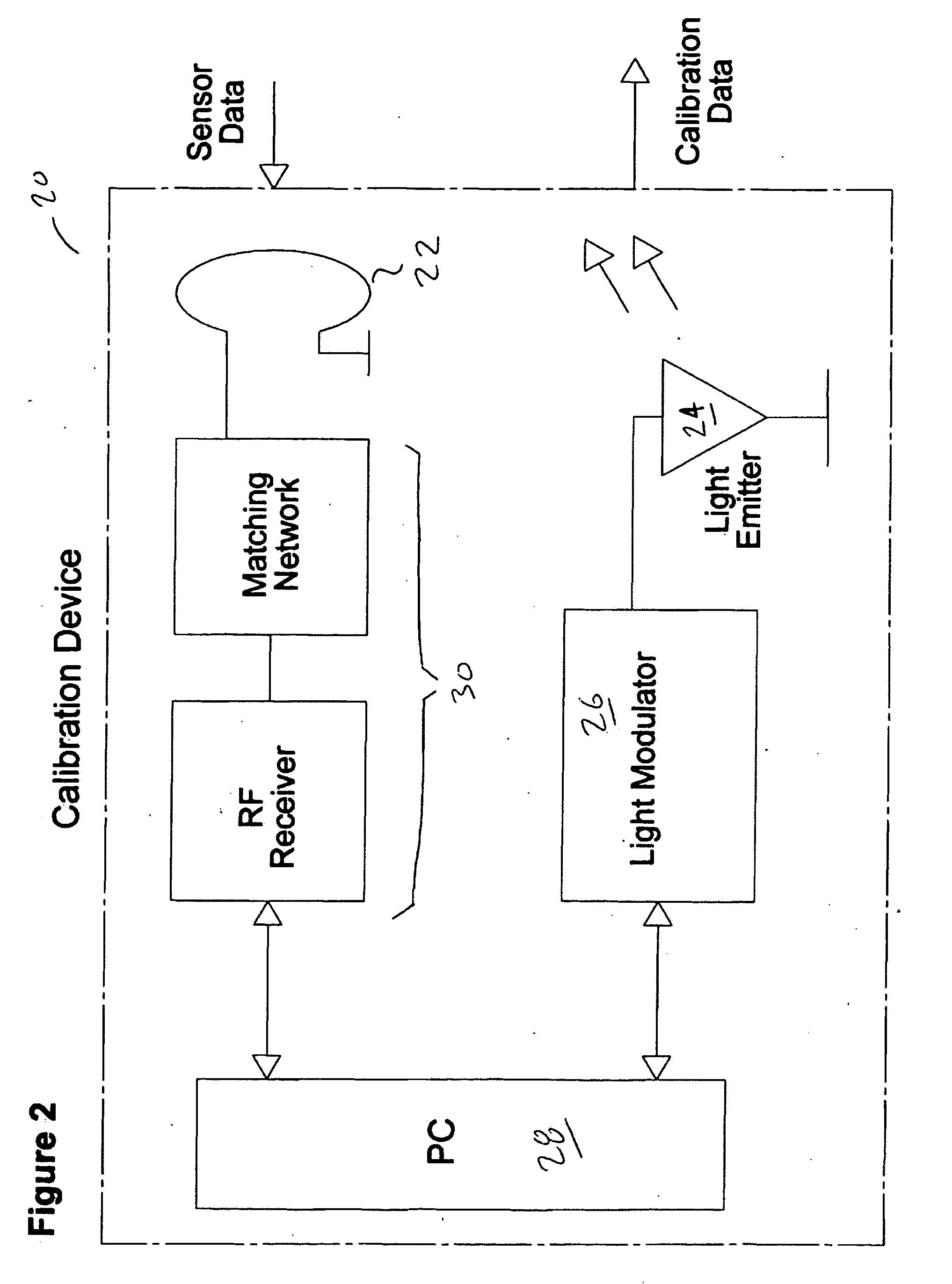
This additional telemetric circuitry is particularly wasteful since two-way communication between a reader and the implant is only required during initial calibration of the implant device shortly after the implant housing sections are hermetically sealed together during its manufacture.
Once the conventional implant device is calibrated and surgically implanted within a patient, several components of the convention two-way
telemetry circuit are no longer used and forever remain within the device as “dead components”, taking up volume and continuing to consume, measurable, albeit small amounts of limited on-board power.

