Filtration device

Active Publication Date: 2020-05-21
MURATA MFG CO LTD
View PDF0 Cites 2 Cited by
  • Summary
  • Abstract
  • Description
  • Claims
  • Application Information

AI Technical Summary

Benefits of technology

This patent text describes a configuration that helps prevent clogging of filters and reduces bubbling of fluids. This is achieved by increasing the velocity of fluid through a third channel that faces the filter, while minimizing an increase in velocity across the entire channel. This configuration also helps maintain the activity and integrity of cells that are being filtered. Overall, this invention helps prevent the filter from becoming clogged and ensures a smooth filtering process.

Problems solved by technology

If the fluid to be filtered has low velocity, the target substance does not readily detach from the filter after coming into contact with the filter, and is thus likely to clog the filter.

Method used


Image

  • Filtration device
  • Filtration device
  • Filtration device

Examples


embodiment 1

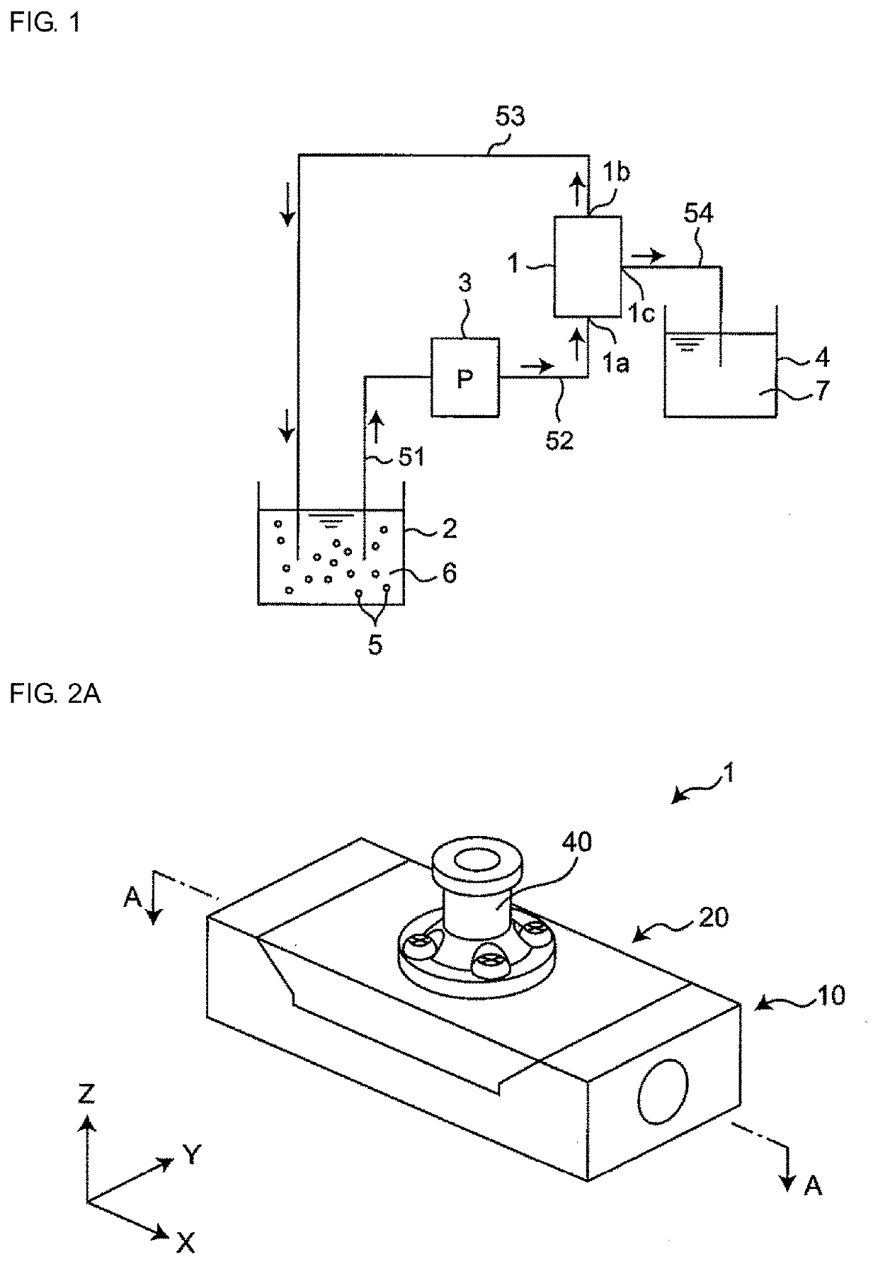
[0074]FIG. 1 schematically illustrates an example of how a target substance 5 is separated by filtration using a filtration device 1 according to Embodiment 1 of the present invention. As illustrated in FIG. 1, the filtration device 1 is a cross-flow filtration device. The filtration device 1 admits a fluid 6 including the target substance 5 through a fluid inlet 1a, and discharges the fluid 6 through a fluid outlet 1b. The filtration device 1 filters a portion of the fluid 6 flowing from the fluid inlet 1a to the fluid outlet 1b, and discharges, through a filtrate outlet 1c, a fluid (to be referred to hereafter as filtrate) 7 from which the target substance 5 has been removed by the filtration.

[0075]The fluid 6 including the target substance 5 is received in a fluid tank 2. The fluid 6 in the fluid tank 2 is drawn into a pump 3 through a pipe 51, and then supplied by the pump 3 to the fluid inlet 1a of the filtration device 1 through a pipe 52. The fluid 6 discharged through the fl...


PUM

PropertyMeasurementUnit
Areaaaaaaaaaaa

Abstract

A filtration device includes a first channel member, a second channel member, and a filter. The first channel member has a recess recessed inward from an outer wall surface. A groove is formed is the recess and has an opening in a recessed surface of the recess. First and second channels, each defined by a through-hole, are formed in the first channel member and are connected to the groove. A first connection part connects the groove with the first channel. The second channel member has a projection that detachably mates with the recess. The second channel member includes a discharge channel that has an opening in a projecting surface of the projection, the opening being located over the groove. The filter is disposed along the groove, and positioned at the opening of the discharge channel. When the first and second channel members are placed in a operative relationship, a third channel is formed by the projecting surface of the projection and the opening of the groove. The third channel is connected to the first channel via the first connection part. The third channel at which the filter is positioned has a smaller cross-sectional area than the first channel.

Description

CROSS REFERENCE TO RELATED APPLICATIONS[0001]The present application is a continuation of International application No. PCT / JP2018 / 031304, filed Aug. 24, 2018, which claims priority to Japanese Patent Application No. 2017-183884, filed Sep. 25, 2017, the entire contents of each of which are incorporated herein by reference.TECHNICAL FIELD[0002]The present invention relates to a filtration device that separates a target substance included in a fluid from the fluid.BACKGROUND OF THE INVENTION[0003]Japanese Examined Patent Application Publication No. 6-57254 (hereinafter “Patent Document 1”) discloses a filtration device with a circulating system. The circulating system includes a container containing a liquid including blood components, and a ceramic filter. The filtration device is used for cross-flow filtration of the liquid including blood components.[0004]The filtration device disclosed in Patent Document 1 has problems described below. If the fluid to be filtered has low velocity...

Claims


Application Information

Patent Timeline
IPC IPC(8): B01D46/00B01D12/00
CPCB01D12/00B01D2311/04B01D2201/32B01D46/005B01D2311/25A61M1/34A61M1/3635C12M47/00
Inventor KAWAGUCHI, TOSHIKAZUBANJU, MASARUKONDO, TAKASHI
Owner MURATA MFG CO LTD
Why Eureka
Try Eureka