Method and system for treating sewage sludge

Inactive Publication Date: 2012-08-02
TECHNION RES & DEV FOUND LTD
View PDF1 Cites 4 Cited by
  • Summary
  • Abstract
  • Description
  • Claims
  • Application Information

AI Technical Summary

Benefits of technology

[0059]According to some embodiments of the invention, the atomizer comprises a rotating part configured for reducing clogging of the atomizer by particles of the fuel in the suspension.

Problems solved by technology

The sludge can be disposed of in a landfill, but this requires considerable landfill space due to the large amounts of sewage sludge produced by modern societies.
In addition, the presence of heavy metals, disease-causing microorganisms and / or parasites in sludge creates a health hazard.
Digestion is a slow and costly process, taking up to 30 days for anaerobic digestion.
In addition, aerobic digestion typically requires aeration, which increases operating costs.
Incineration of sludge is problematic due to the high energy costs involved and the pollutants in the emissions, and is therefore not commonly used for sludge treatment and disposal.
Incineration of sludge is not a cost effective method of producing energy, because of the large amount of energy needed to dry the sludge before the organic matter can be incinerated.
Methods which utilize dried or partially dried sewage sludge have the drawback of requiring prior removal of some or all of the water from the sludge.
Such a procedure (e.g., evaporation of the water by heating) typically involves high energy consumption, as well as additional time and equipment.

Method used


Image

  • Method and system for treating sewage sludge
  • Method and system for treating sewage sludge
  • Method and system for treating sewage sludge

Examples


example 1

Sewage Sludge Treatment System with Combined Cycle Power Generation

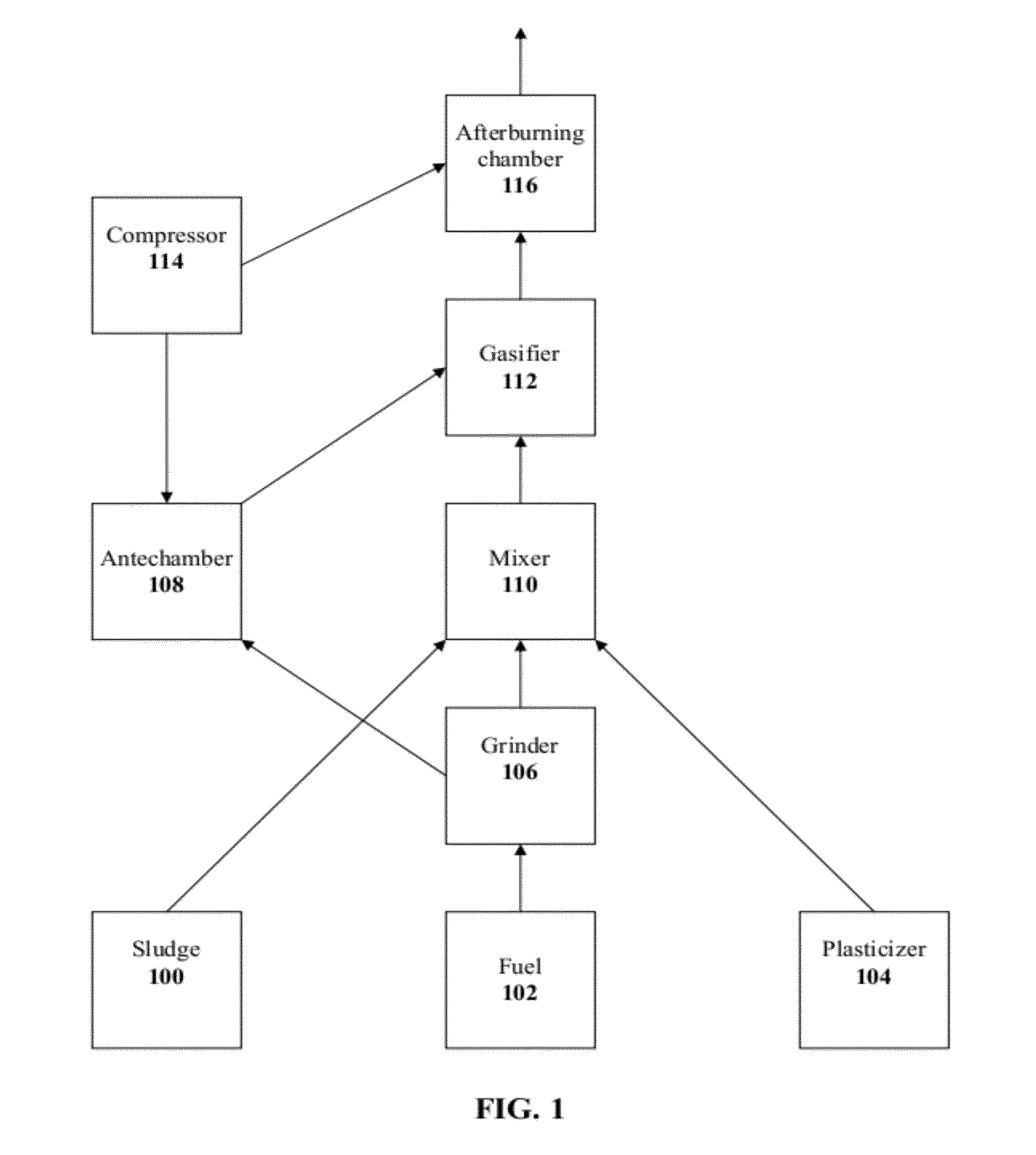
[0150]FIG. 3 shows a scheme of an exemplary system which combines treatment of sewage sludge and power generation. FIG. 3 shows the basic components as shown in FIG. 1, with the addition of more details, including a combined cycle comprising gas turbine 350 and steam cycle 390 for generating power.

[0151]The system comprises a grinder 300 (e.g., a colloidal mill) for grinding a solid fuel (e.g., coal) in solid form or as a slurry. Grinder 300 receives fuel through an inlet 302, and ground fuel exits through an outlet 304 to both a mixer 310 and an antechamber 320. Mixer 320 receives fuel through an inlet 312 and sludge through an inlet 314, and optionally also plasticizer through an optional inlet 316. Mixer 310 produces a suspension of ground fuel in sludge, optionally stabilized by the plasticizer, which exits through an outlet 318 to a gasifier 330. An antechamber 320, which operates as a combustion chamber, receiv...

example 2

Unified Module for Gasification and Combustion

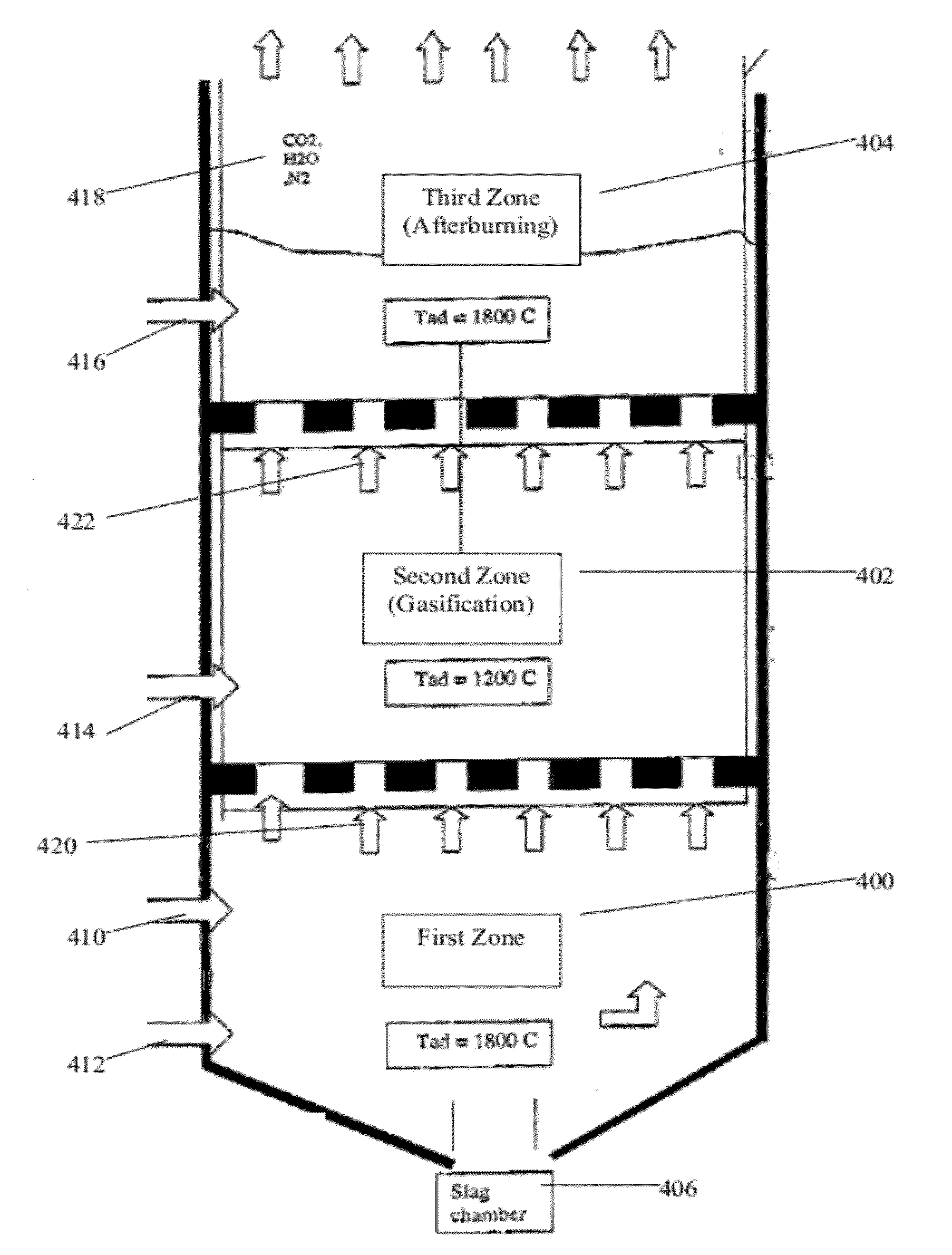
[0153]FIG. 4 depicts an exemplary furnace comprising three zones, which can perform gasification of sewage sludge and combustion of the gas produced by gasification.

[0154]A first zone 400 receives solid, liquid and / or gaseous fuel (e.g., coal, gas, gasoline) and oxygen (e.g., air) via suitable inlets 410 and 412, and the fuel undergoes combustion therein, resulting in a temperature of about 1800° C. Slag remaining from combustion falls into a slag chamber 406, and can be readily disposed of.

[0155]A second (gasification) zone 402 receives a fuel / sewage sludge suspension via a suitable inlet 414, as well as heat and hot combustion products 420 from the first zone. The temperature in second zone 402 is about 1200° C., at which temperature the suspension is gasified readily to CO and H2 gas. Optionally, second zone 402 receives fuel and sewage sludge (and optionally a plasticizer) via separate inlets (not shown), and further comprises a mixe...


PUM


Abstract

A method and system for treating sewage sludge are described herein. A carbonaceous fuel is mixed with sewage sludge, the mixture is then gasified, and the obtained gas is combusted. The method and system may utilize wet sewage sludge.

Description

FIELD AND BACKGROUND OF THE INVENTION[0001]The present invention, in some embodiments thereof, relates to sewage treatment and more particularly, but not exclusively, to a method and system for treating sewage sludge.[0002]Sewage treatment typically involves formation of sewage sludge by separating solids from the bulk of the wastewater. Sewage sludge typically contains approximately 90-95% water, the balance being mostly solid organic matter. The sludge can be disposed of in a landfill, but this requires considerable landfill space due to the large amounts of sewage sludge produced by modern societies. In addition, the presence of heavy metals, disease-causing microorganisms and / or parasites in sludge creates a health hazard.[0003]In many cases, sludge is treated by being subjected to digestion by microorganisms, in order to reduce the amount of organic matter and the number of disease-causing microorgansims in the sludge. Digestion may be anaerobic or aerobic. Digestion is a slow ...

Claims


Application Information

Patent Timeline
IPC IPC(8): F27D3/00F02C3/20F02G3/00
CPCC02F11/06Y02E20/16C02F2303/10Y02W10/30Y02W10/40
Inventor BORODYANSKI, GENADYKIRZHNER, FELIXZIMMELS, YORAMZIMMELS, TOMER
Owner TECHNION RES & DEV FOUND LTD
Why Eureka
Try Eureka