Portable Balloon Filling Device and Method

Inactive Publication Date: 2012-03-22
RAMERE DONNA A +1
View PDF4 Cites 13 Cited by
  • Summary
  • Abstract
  • Description
  • Claims
  • Application Information

AI Technical Summary

Benefits of technology

[0009]The gasket is placed between the fill head and the container to prevent fluid leaks wherein the gasket material is selected from the group consisting of paper, rubber, silicone, compressed fiber, grease, metal, plastic, cork, felt, neoprene, nitrile rubber, polytetrafluoroethylene, and combinations thereof.
[0010]The nozzle includes at least one barb of a sufficient size and dimension to prevent a balloon from disengaging the barb while the balloon is being filled with fluid.
[0011]In addition, the device includes a pickup tube having one end that communicates with the nozzle and a second end that contacts liquid in the container. A screen is secured to the second end of the pickup tube to reduce clogging the pickup tube, trigger mechanism, and nozzle with foreign objects.
[0015]The nozzle includes at least one barb of a sufficient size and dimension to prevent a balloon from disengaging the barb while the balloon is being filled with fluid.
[0016]The device further comprises a pickup tube having one end that communicates with the nozzle and a second end that contacts liquid in the container. A screen is secured to the second end of the pickup tube to reduce clogging the pickup tube, trigger mechanism, and nozzle with foreign objects.

Problems solved by technology

Filling balloons with liquid, typically water, for recreational purposes is a popular pastime activity, yet filling balloons with liquid is often cumbersome, messy, and sometimes painful.
These sources also often suffer from sharp edges and threads that also promote balloon breakage.
These sources suffer from additional limitations, such as not being portable and not providing water in a pressure range conducive to filling balloons.
A high residential water pressure also leads to broken balloons, resulting in unwanted mess, wasted water, and the potential for injury when balloons break in a filler's hands.
These sources are also stationary, therefore necessitating multiple trips to the water source.
This is often impracticable due to large distances between recreation sites and the fixed water source, resulting in long times spent away from the recreational site, a disincentive to engage in balloon-filling activities, and severely limiting the locations of recreational sites.
Specifically, there is a need for a portable balloon filling system with a self-contained fluid reservoir that is capable of being pressurized, capable of repeatedly filling a balloon with fluid, yet does not promote balloon breakage.

Method used


Image

  • Portable Balloon Filling Device and Method
  • Portable Balloon Filling Device and Method
  • Portable Balloon Filling Device and Method

Examples


Embodiment Construction

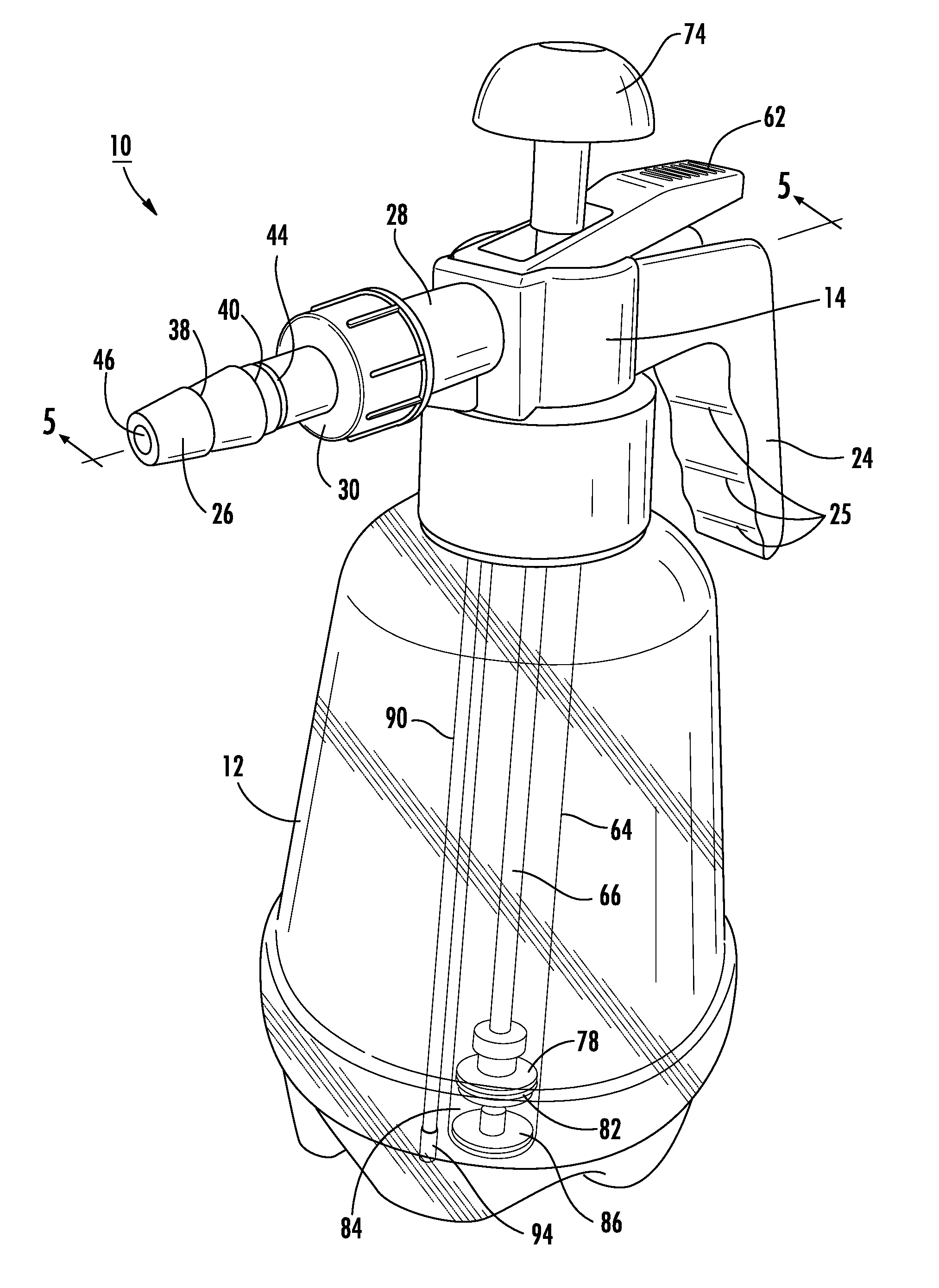
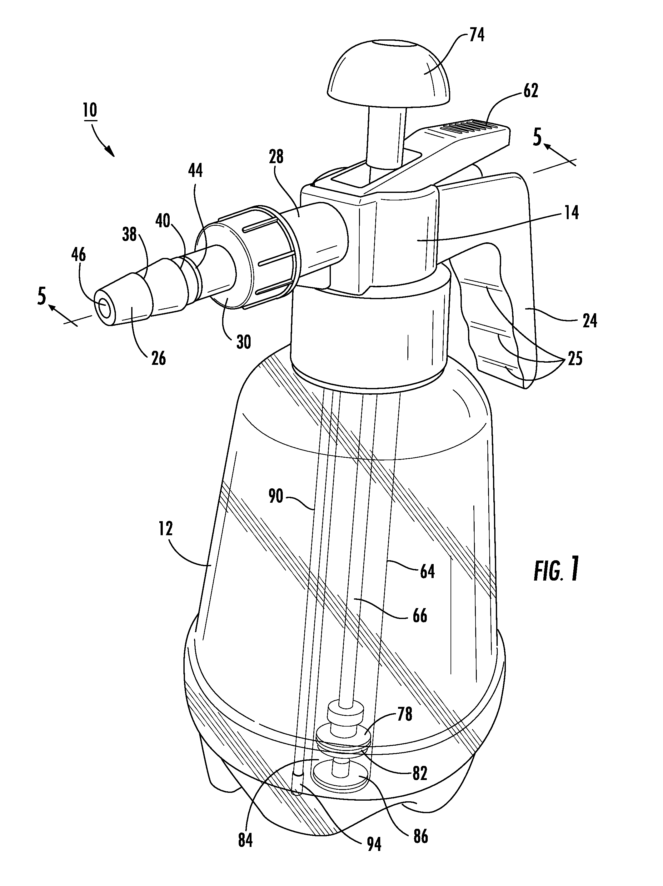
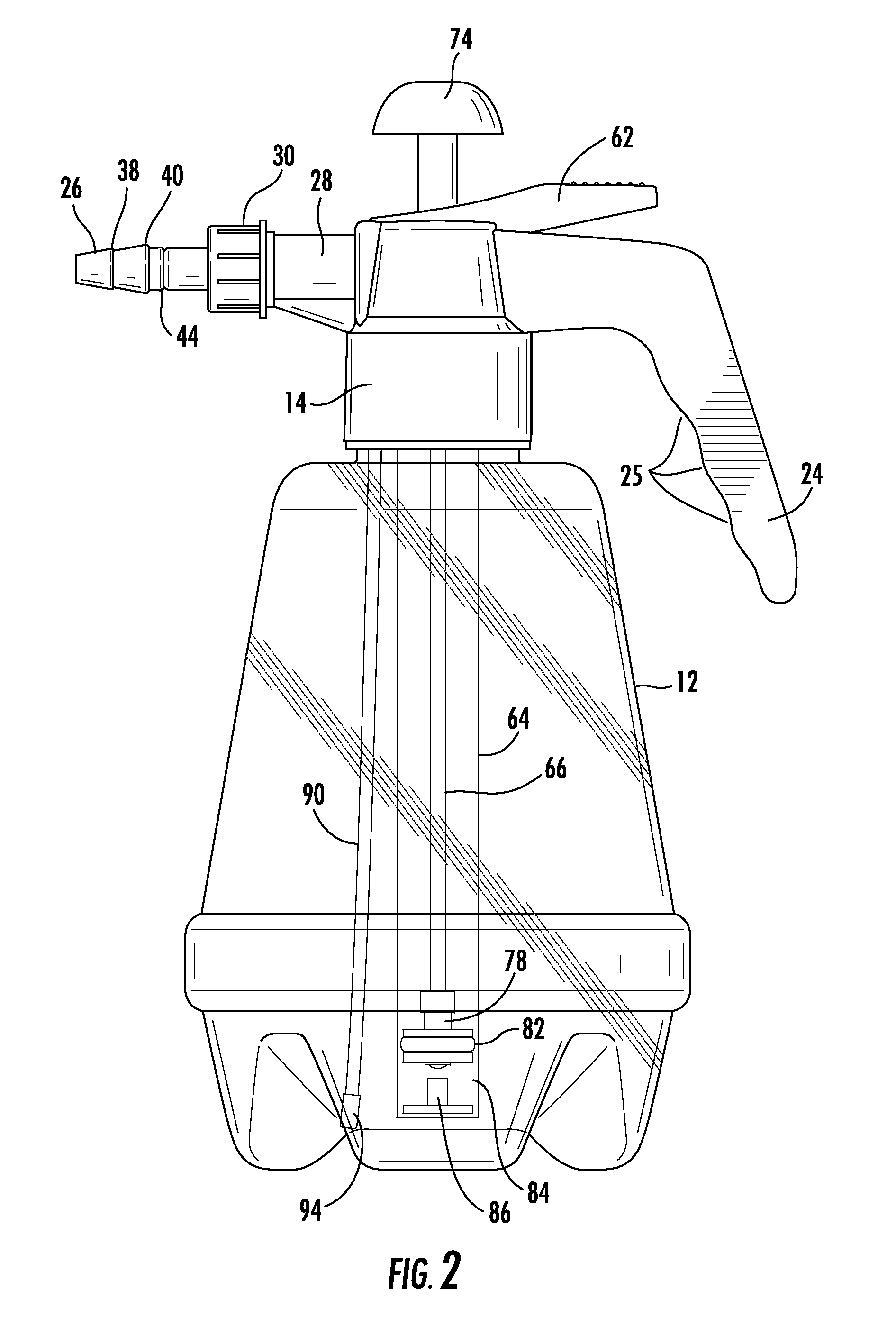
[0033]The present invention will now be described more fully hereinafter with reference to the accompanying drawings, in which preferred embodiments of the invention are shown. This invention may, however, be embodied in many different forms and should not be construed as limited to the embodiments set forth herein. Rather, these embodiments are provided so that this disclosure will be thorough and complete, and will fully convey the scope of the invention to those skilled in the art. Like numbers refer to like elements throughout. Alternate embodiments of an element are notated with lowercase letters.

Overview of the Device

[0034]Referring initially to FIG. 1 and FIG. 2, in one embodiment of the invention, the two central components of the balloon pump 10, are a container 12 capable of being pressurized, and a filling head 14. The filling head 14 is capable of being sealedly secured to the container 12 so that the container, once pressurized, is able to maintain a pressurized state.

[...


PUM

PropertyMeasurementUnit
Sizeaaaaaaaaaa

Abstract

A device and method for filling balloons with a fluid comprising a pressurizable container and a filling head. The device pressurizes a container filled with a fluid and releases the fluid through a barbed nozzle that engages a balloon. To use the device, a user engages a balloon on a barbed nozzle attached to the filling head and pumps a pumping mechanism. When the container is adequately pressurized, a user actuates a trigger mechanism that releases fluid in the pressurized container into a balloon engaged on a nozzle to fill the balloon with the fluid

Description

CROSS-REFERENCE TO RELATED APPLICATIONS[0001]This application is a Continuation in Part of U.S. application Ser. No. 12 / 877,502, filed Sep. 8, 2010 which claims the benefit of U.S. Provisional Application No. 61 / 249,335, filed Oct. 7, 2009, the disclosures of which are hereby incorporated by reference herein in their entireties all commonly owned.FIELD OF THE INVENTION [0002]The present invention is directed toward a system and method for filling balloons with a liquid. More specifically, the invention relates to a portable balloon filling station that allows users to easily fill balloons with liquid contained within the system.BACKGROUND OF THE INVENTION[0003]Filling balloons with liquid, typically water, for recreational purposes is a popular pastime activity, yet filling balloons with liquid is often cumbersome, messy, and sometimes painful.[0004]A fixed water source such as a kitchen faucet or garden hose often has a relatively large opening that stretches the mouth of a water b...

Claims


Application Information

Patent Timeline
IPC IPC(8): B65B3/04
CPCA63H2027/1033A63H27/10
Inventor RAMERE, DONNA A.GLENN, ALEXIS N.
Owner RAMERE DONNA A
Why Eureka
Try Eureka