Multifunctional torque wrench

Active Publication Date: 2020-05-21
HU BOBBY
View PDF0 Cites 0 Cited by
  • Summary
  • Abstract
  • Description
  • Claims
  • Application Information

AI Technical Summary

Benefits of technology

[0009]With such configuration, the operation member is switchable between different positions with respect to the main body. When the operation member is at the first position, the extension portion is turned to rotate with respect to the main body, so as to drive the fastener for fastening or loosening, with the torque displayed by the indication device. When the wrench is to be stored, the operation member is switched to the second position, the second axis of the extension portion is in parallel to the first axis of the main body, so as to minimize the volum

Problems solved by technology

However, due to the structural limitation, the conventional torque wrench 1 merely achieves a singular function.
In the bicycle industry, such product will be possibly purchased only by the professional m

Method used


Image

  • Multifunctional torque wrench
  • Multifunctional torque wrench
  • Multifunctional torque wrench

Examples


first embodiment

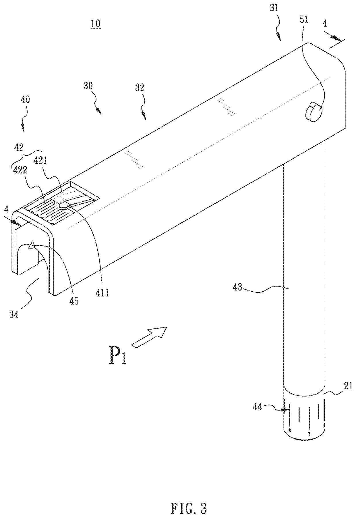
[0025]Referring to FIG. 2 to FIG. 9, the multifunctional torque wrench 10 comprises a main body 20, an operation member 30, and an indication device 40. The multifunctional torque wrench 10 is applied for driving a fastener A (as shown by FIG. 4).

[0026]The main body 20 has a driving portion 21, a combination portion 22, and a twisting portion 23 disposed between the driving portion 21 and the combination portion 22. The main body 20 has a first axis L1 passing through the driving portion 21, such that the driving portion 21 drives the fastener A about the first axis L1.

[0027]The operation member 30 has a connection portion 31 and an extension portion 32 connected with the connection portion 31. The connection portion 31 is connected with the combination portion 22 of the main body 20, such that the operation member 30 is able to be switched between the first position P1 (as shown by FIG. 3 and FIG. 4) and a second position P2 (as shown by FIG. 5 and FIG. 6). The extension portion 32...

second embodiment

[0035]Referring to FIG. 10 and FIG. 11, the multifunctional torque wrench 10 is illustrated. The pointer 41 has a resilient plate 412, and the pointer 41 is in the groove 33 and resisted by the resilient plate 412. The resilient plate 412 has one end connected with the extension portion 32 and raised along a slanting direction, with another end of the resilient plate 412 contacting the pointer 41 for resisting the pointer 41, whereby the pointer 41 is resisted by the resilient plate 412 for pressing the indication end 411 on the mark portion 422. Therefore, when the operation member 30 is at the first position P1 or the second position P2, the pointer 41 is maintained at the stable position, preventing a loosened or wavering possibility thereof.

[0036]Further referring to FIG. 12 and FIG. 13, the third embodiment of the multifunctional torque wrench 10 is illustrated. The pointer 41 further has a resilient plate 413, and the pointer 41 is in the groove 33 and resisted by the resilien...


PUM


Abstract

A multifunctional torque wrench includes a main body, an operation member, and an indication device. The main body has a driving portion, a combination portion, and a twisting portion. The driving portion pivotally drives a fastener to rotate about an axis passing through the main body. The operation member is switchable between a first position and a second position with respect to the main body. The extension portion extends along a second axis. When the operation member is at the first position, the second axis is vertical to the first axis, allowing a user to turn the main body to generate the torque for driving a fastener. The indication device is disposed between the main body and the operation member for displaying the torque value. When the operation member is at the second position, the second axis is parallel to the first axis for storage.

Description

BACKGROUND OF THE INVENTION1. Field of the Invention[0001]The present invention relates to torque wrenches, and more particularly, to a multifunctional torque wrench.2. Description of the Related Art[0002]Referring to FIG. 1, a conventional torque wrench 1 for bicycle maintenance is provided, comprising a handle 2 and a hexagonal wrench 3. The hexagonal wrench 3 has one end disposed on the handle 2, such that the torque wrench 1 is present in a T shape. The hexagonal wrench 3 has another end provided with a socket head 4, so that the user is allowed to twist the hexagonal wrench 3 by turning the handle 2, whereby the socket head 4 drives the mounted screw or driver head to rotate (not shown). The torque wrench 1 has a point member 5 and an indication panel 6. When the hexagonal wrench 3 is twisted by the user turning the handle 2, the point member 5 moves with respect to the indication panel 6 for pointing at the corresponding scale on the indication panel 6, so as to acquire the to...

Claims


Application Information

Patent Timeline
IPC IPC(8): B25B23/00B25B23/142
CPCB25B23/1427B25B23/0078B25B23/0028B25B13/06B25B23/0042
Inventor HU, BOBBY
Owner HU BOBBY
Why Eureka
Try Eureka